Update: Nov 7th
After a few months of working with the enclosure on a regular basis, I've discovered many shortcomings, listed below. It's definitely a start in the right direction, but will probably take a good while to refine this into a proper product.
- The ultrasonic humidifier, while a really great concept, doesn't actually humidify the air in the chamber. It fills it with mist, but the mist doesn't evaporate. Instead, it settles and soaks into the substrate, resulting in standing water. Possible solutions include:
- Drain holes
- Infrequent use of humidifier
- Add soil moisture sensor
- PID controller code
- Use evaporative / wicking humidifier instead
- Fresh air exchange conflicts with humidity. Each time the air is cycled by the fans, humidity is lost.
- A near 100% humidity environment is very hard on the SCD30 sensor package, and at $60 each, it's is difficult to justify the short lifespan achieved in these conditions. Perhaps CO2 measurement isn't worth it, and something like the SHT30 will have to suffice.
- Raspberry Pi devices are difficult to get, but are ultimately the best platform with a full Linux OS and ethernet.
- Testing with traditional microcontrollers + ESP32 wifi using CircuitPython did not go well due to instability, library limitations, and a lack of memory.
- For my second enclosure build, the shift register was combined with the fan tachometer circuit on the same board. Unfortunately, the automation is switching different outlets each time, as if the wrong number of bits are being shifted. Electronics are hard.
While recently attending the Ohio Mushroom Festival, one of the speakers described a revelation that essentially amounts to the difference between "What can the mushroom do for me?" and "What can I do for the mushroom?"
Instead of trying to achieve success by forcing a particular formula of air and humidity, perhaps I should pay more attention to the mushroom itself.
I have done away with sensor-based logic altogether at this point, and instead turn the fan and humidifier on at timed intervals. The fan exchanges the enclosure's air for 60 seconds, followed by 60 seconds of misting. This cycle repeats every 30 minutes. I'm not sure this is enough humidity to induce pinning.
When I have more of this figured out, I'll create a new post detailing a better enclosure build that solves these problems. Until then, have a look below to see how I got to this point.
/update
During my first batch of oysters, I ran into some trouble getting the correct ratio of humidity and air flow. It was pretty frustrating because it seemed like striking the correct balance meant babysitting the enclosure all day. Taking the lid off to get oxygen to the fruit, but then you just let out all the humidity, so you need to mist more. I feel like I should have been doing something every 20 minutes or so. When was I going to sleep? As a software developer and failed electrical engineer, I knew it was time for... AUTOMATION! What a great excuse to dive back into electronics.
One maxed out credit card later (thank you, adafruit.com)...
Wait, no, not like that. What are you doing? We're growing mushrooms, not starting an electronics business... right? ...right?
In the name of R&D, I bought enough electronics gear to make basically anything ever, except, apparently, a TD-303 synth clone... maybe one day.
I found some inspiration, and figured I could probably do all those things, too. I dove in and started wiring things together, and somehow it ended up with a working product.
If you're not into DIY electronics, but still want an automated fruiting chamber, North Spore sells the Mella Smart Mushroom Fruiting Chamber. I haven't purchsed or used one, or even seen the video, I just know they exist and thought it would be worth mentioning.
Here are the main components of the enclosure automation system.
Switched Outlets Box
Check out the details of the full build here, or if you want to save yourself the trouble, you can just buy one instead. This linked product has a bunch of safety features listed, and I'm sure mine doesn't have any of them unless they are already part of the relay bank board. The only thing I know about the board is that it uses optical isolators to seperate the AC voltages from the control pins. These devices are basically just an IR LED pointed at an IR receiver packaged into a single IC.
Mistakes made, or, potential improvements:
- One of the 8 outlets should be always-on because I had to plug in the Raspberry Pi further away instead of the imminently convenient relay box.
- For bonus points, there should be a toggle to switch the always-on outlet to a relay-switched outlet.
- And just so long as there's unlimited space in the 4-gange mountable outlet box, can we fit a DC adapter to siphon power for the relay board? This would save us two jumper wires.
- Zero safety features. I'm a little surprised this hasn't caught fire. I don't even think I grounded the box.
- Control wire plugs - the relay board is controlled by jumper wires that I'm hoping don't fall off.
- Maybe put the relay board on the outside / back of the box. Sure was crowded in there with all the 14 ga. wire.
First step is to mount the relay board in the box. After I drilled holes, it occurred to me that I should have bought a set of M2.5 x 0.45mm taps for mounting the standoffs. Maybe there's something else we can use them for.
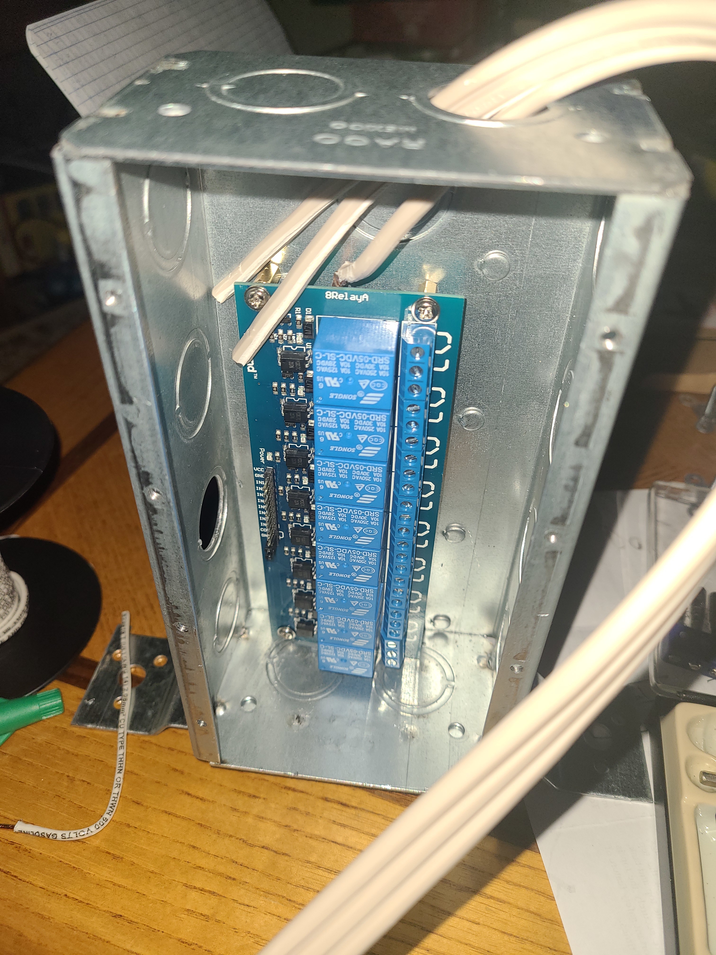
One thing to notice is the knock-out hole right in front of the control pins. This is where our jumper wires will enter the box.
I'm not really a fan of the extension cord I used here. It wasn't meant to be wired to something like this one is. It was difficult to strip the insulator and identify which wires were which during assembly.
Speaking of knock-out holes, they leave a pretty nasty edge around their perimeter. While I was certainly concerned about the high-voltage cord getting nicked, I thought for sure the relay control wires were going to get shredded, so I bought a few flexible cord grips. These really put a nice touch on the finished device, and put my mind at ease.
Here's a pic of the working switch box before I extended the control wires and added the cord grips.
Ah, almost forget the most important mistake I made on this part of the project.
How I blew the mains circuit breaker.
On a relay, there are 3 wiring ports. The one in the middle is for your power input. By default, it is connected to the port on the right, called the "normally-closed" connection. That is to say, unless the relay is engaged, power will flow from your source wire in the middle directly to the NC port on the right without even turning the unit on.
Well I didn't think this through and connected the mains common wire (white) to each of the relay's NC ports. This way, when I plugged the unit in, the breaker tripped immediately as if I had stuck a fork across both outlet terminals... because that's basically what I did. Yikes. I definitely saw light come from inside the box when this happened, but could not find any damage. Lucky.
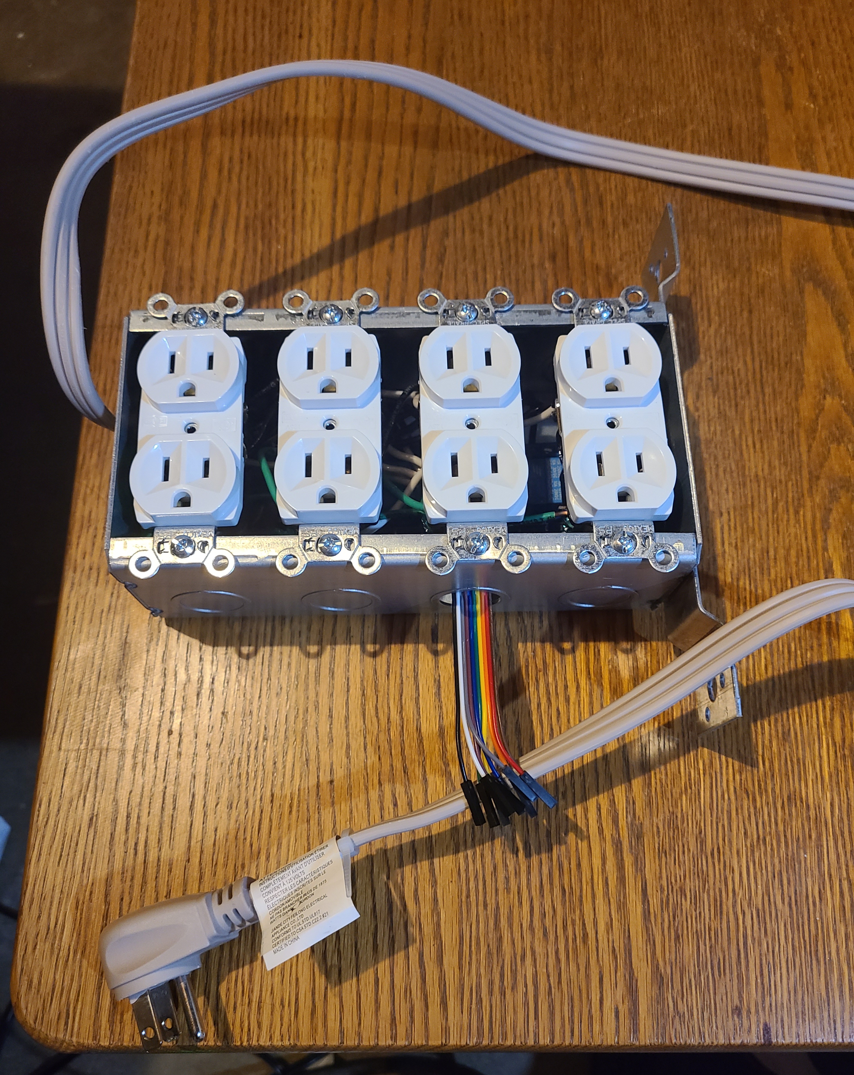
The final wiring of the relays left the NC port empty, the live power source (black) in the middle, and the NO, or "normally-open" port connected to each plug's brass input screw. I broke the jumper tab on all four outlets' input side (but not the common side), allowing for all 8 plugs to be independently operated by a relay. The silver common screws on each outlet were still connected by the jumper tab, so I only needed one common wire for each outlet (a total of 4) instead of one for each plug (a total of 8), saving me a bit of room in the already crowded box.
The last thing to do was connect all 10 jumper wires to the 8 relay control pins, and 2 power pins (VCC and GND). This was much more difficult than it should have been, with the outlets in the way. I should have done this first.
Shift Register
If I had really wanted to, I could have used 8 GPIO pins in the RPi to control the relays. But this seemed wasteful and wouldn't have given me a chance to learn how to use the 74HC595 shift register. I guess I had one of these laying around from an electronics kit, otherwise I'm not sure I would have known to use one here.
A shift register, in short, allows you to control 8 output pins using only 3 input pins. This is done by shifting bits into the register one at a time. Shift registers can be chained together, allowing you to control any number of output pins while only ever using 3 control pins. I won't go into the details here, but this video, among others, was super helpful in showing me how these worked.
I wouldn't recommend this for all chips, but the shift register is simple enough that I wrote my own driver for it.
Here's a pic of the wiring I used for the shift register. This perma-proto board is mounted directly to the enclosure lid, and connected to the switched outlets with extra-long jumpers. I would have loved to use plugs at both ends, but the relay board has a 1x10 pin header, and I don't know how to make any kind of adapter.
As you can see on the left, there is a single column of 8 output pins, one for each relay. The pair of pins at the top is VCC and GND coming from the RPi, and the pair at the bottom is for the relay board. The 3 input pins can be seen between the red jumper wires. Finally, there is a lone capacitor that was suggested in section 9.2 of the datasheet (PDF warning) for smoothing power. Upon further reading, it looks like I should have used another one for the bottom VCC input as well.
Fan Tachometer (Fail)
In addition to the data points collected by the SDC-30 sensor, I wanted to try reading the tachometer data from the 80mm case fan for fresh air exchange after finding out the yellow wire sent pulses generated by the hall effect sensor.
After creating the circuit found in this Electronics StackExchange answer, I was still unable to read the fan pulses. It's probably something simple like changing the Pi's internal pull-up resistor mode on the input pin, but I didn't want to spend any more time on a data point that was ultimately not that important.
The FAE fan is literally always on anyway, since the the temperature never drops below 13°C in the house. Furthermore, "too little CO₂" doesn't exist in the enclosure, rarely dropping below 8 or 900 ppm.
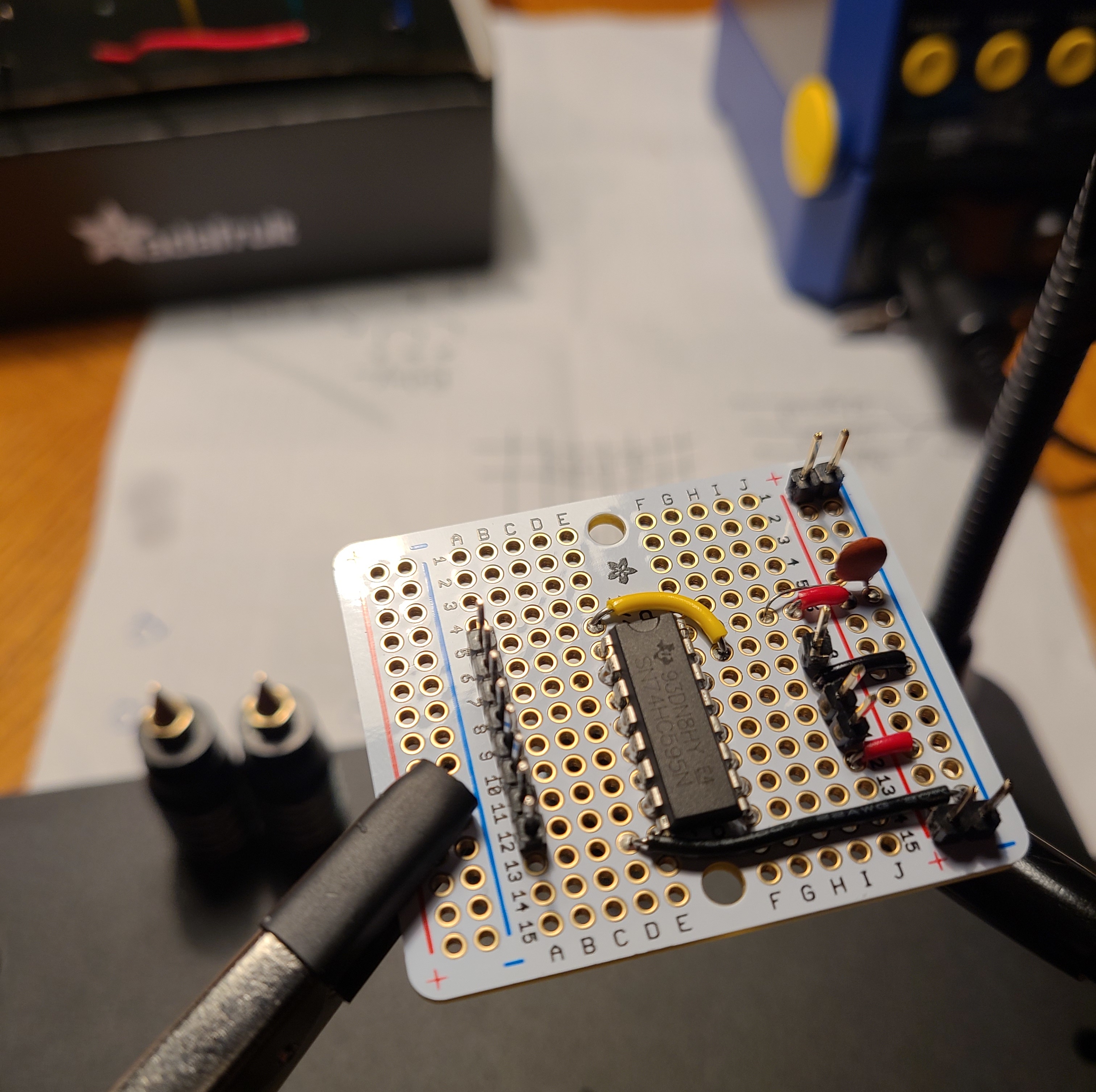
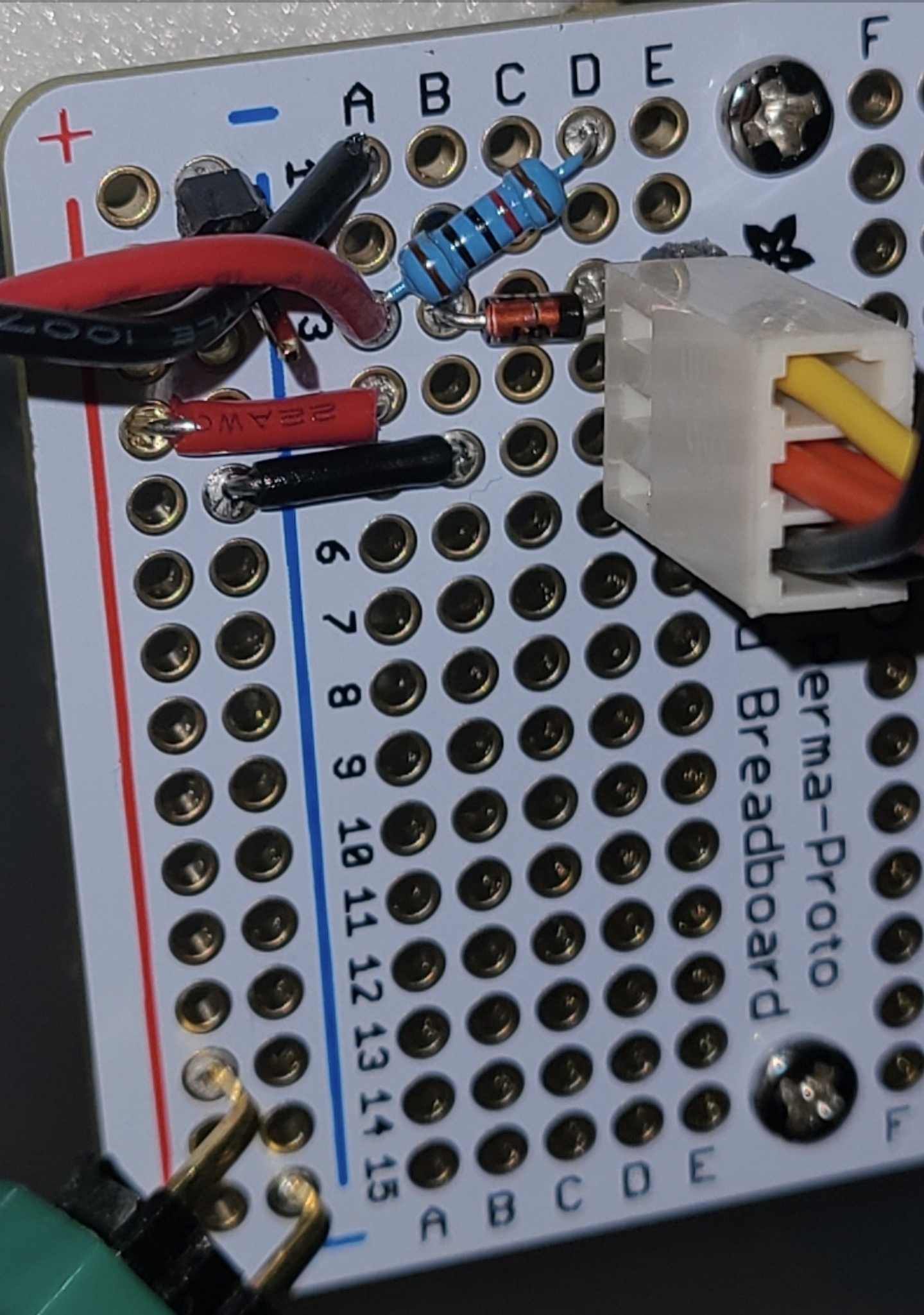
As such, I have made a circuit that almost does something, but doesn't. After poking around with the multimeter (I haven't been able to afford a proper oscilloscope yet), I found some parts of the circuit that seem to fluctuate the way I'm looking for, but I've already fried one RPi by shorting the 3.3v and 5v VCC pins, so I'm particularly careful these days. Here is a close up of my attempt to replicate the circuit from that StackExchange answer.
The black wire in hole A1 is connected to the RPi VCC, and the red wire in A3 is connected to a GPIO pin. The header pin sticking out of the blue '-' column was connected to RPi GND. The result was simply a constant voltage.
SDC-30 Sensor - CO₂ / Humidity / Temp
This chip is the work horse of our enclosure. It collects all the relevant data for making decisions about which outlets to turn on and off. It communicates using the I²C protocol which, while fascinating, is not something I wanted to spend time implementing. So instead I just installed the sdc30_i2c package with pip3. The SDC30 driver source code is worth a read for a better understanding of I²C.
I did not, however, use the STEMMA QT / Qwiic-compatible port on the chip's breakout board. Instead, I stubbornly soldered female headers to the board, which I regretfully had to take out to replace with male headers. At least I got some practice with the solder extractor.
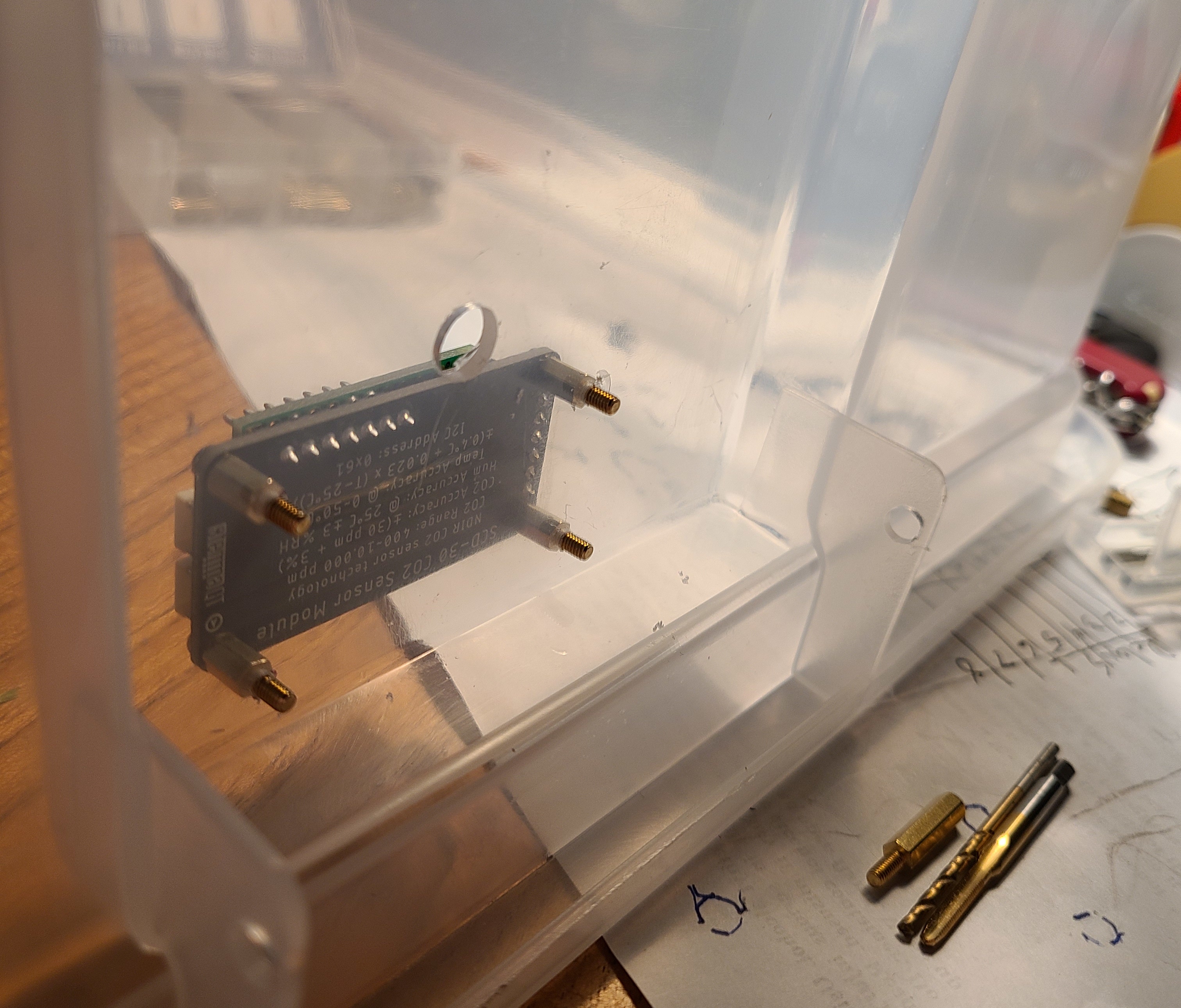
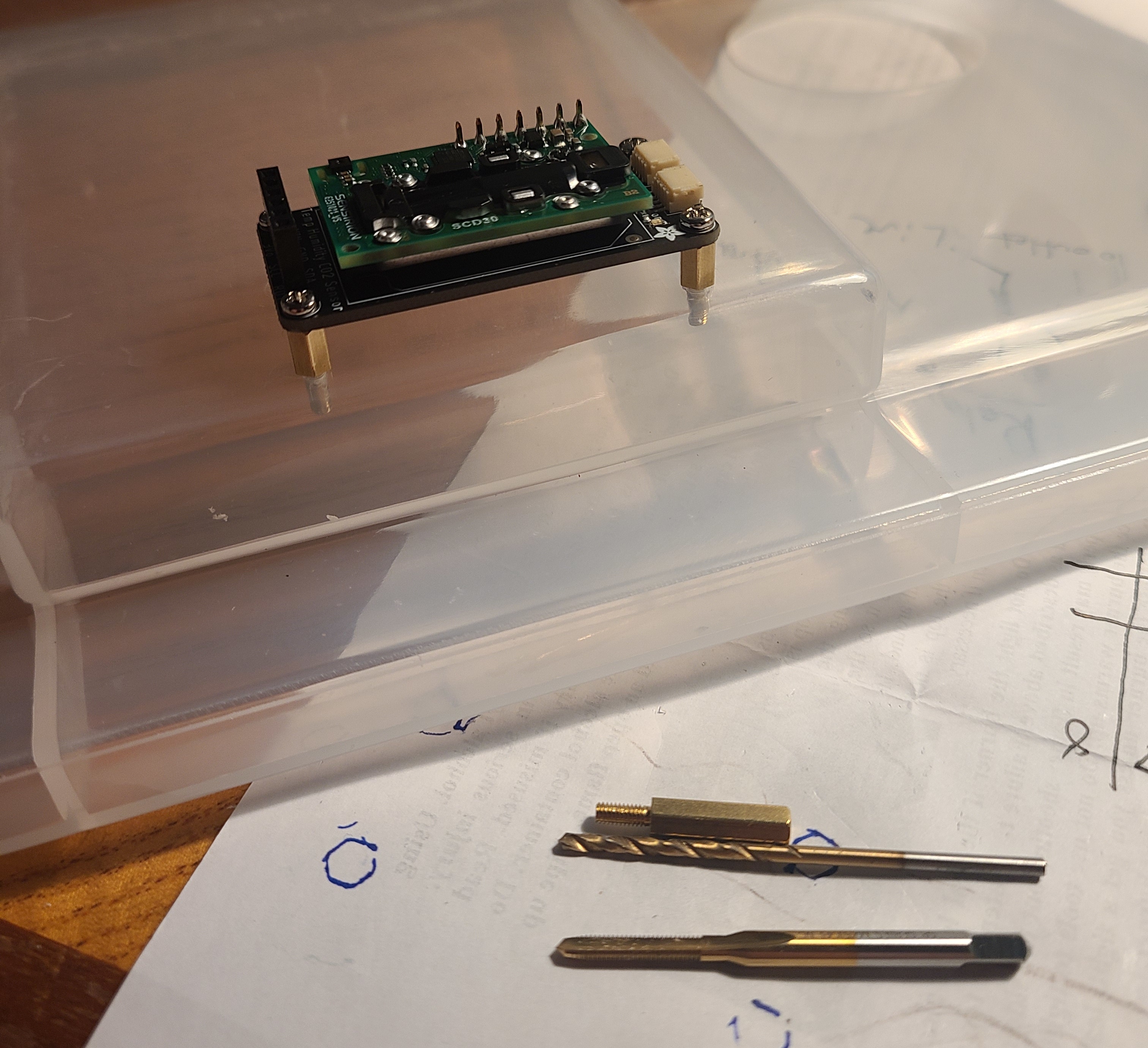
Like all of the boards I mounted to the enclosure's lid, I used the M2.5 x 0.45mm taps so I could screw the standoffs directly into the plastic instead of using nuts. It worked surprisingly well. Here's a picture of the mounted sensor from both sides so you can see its lack of nuts.
Raspberry Pi - Putting it all together
The Raspberry Pi makes this project very easy. It's a full Linux OS, so not only can I easily run a Python script for automation, I can run it as a systemd service and write its data to an NFS share. I can also easily take pictures with the camera module to allow for time lapse video. It has a quad core processor that lets me run true multiprocessing (oh yeah, did Python ever fix the GIL problem? sigh), which makes the code much easier to manage.
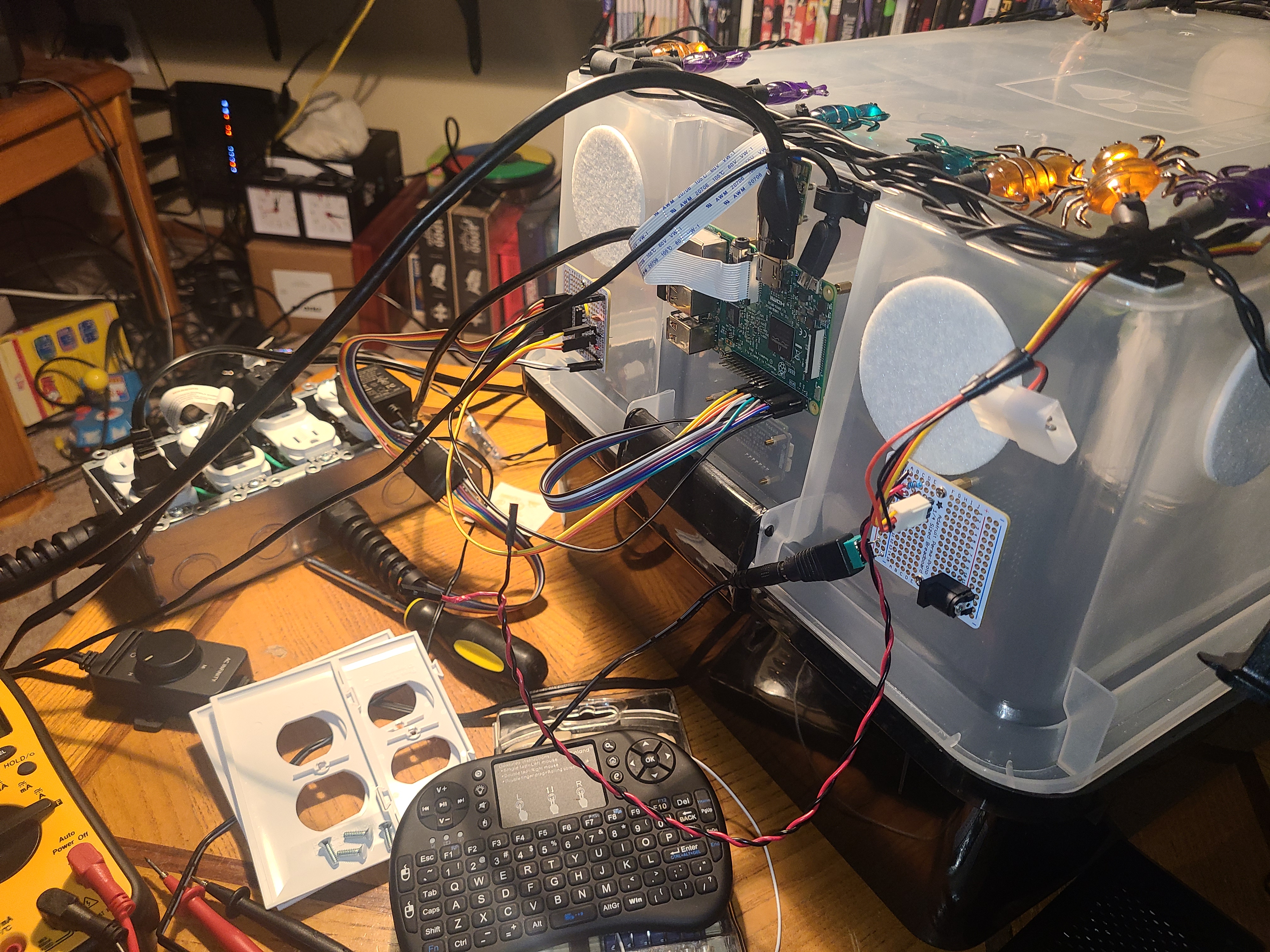
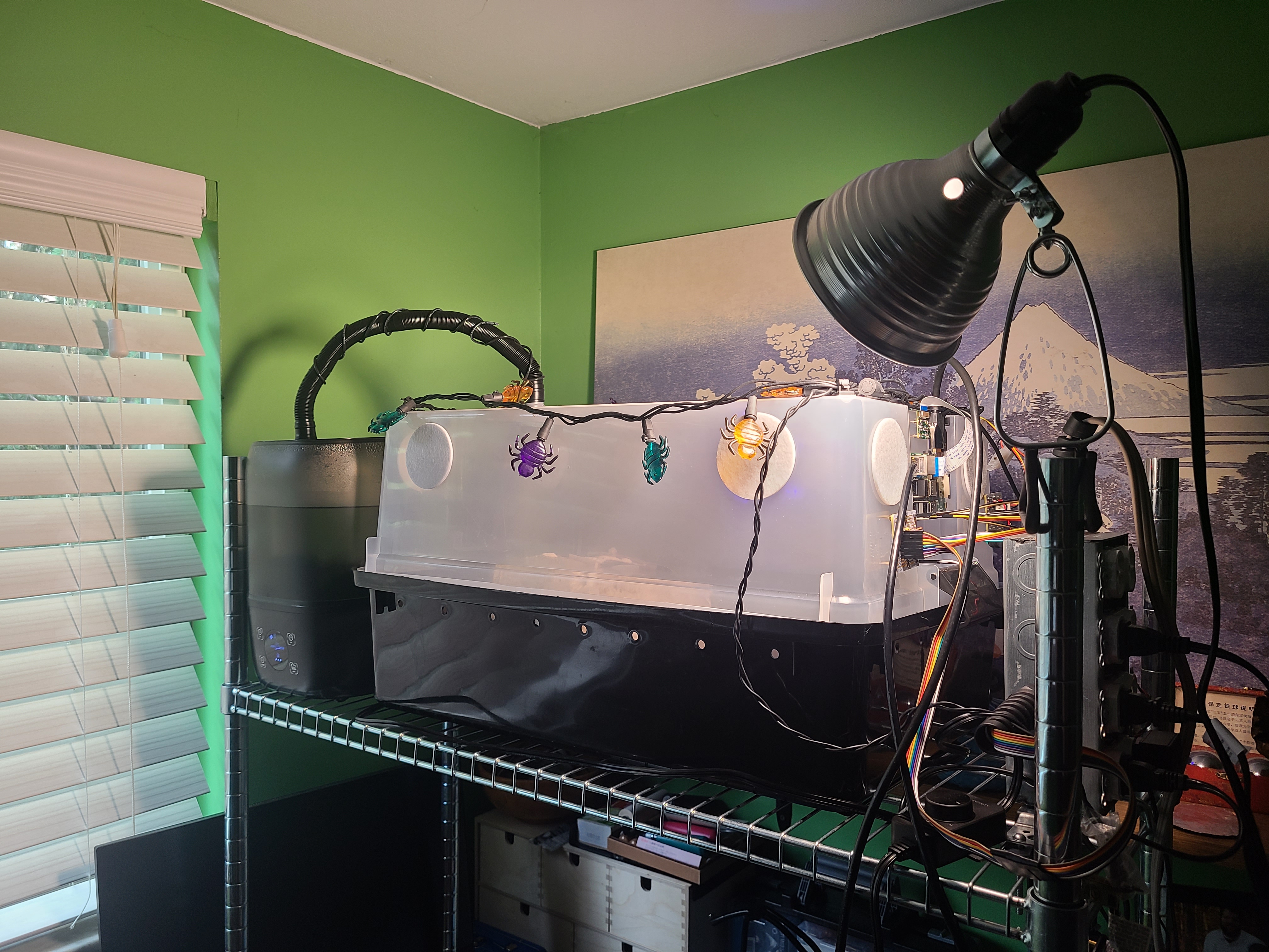
Here is the assembled lid, mostly ready for deployment. The mounted RPi camera is hidden behind the HDMI cable in this pic.
And here's the final deployment, complete with a blue oyster fruiting block from North Spore.
Source Code
More than an electronics project, this has become a full-on software development and Linux administration project.
A detailed analysis of the code is outside the scope of this post, but I'll give a good overview that describes the major parts.
The enclosure service is responsible for collecting data and making decisions. It's the core of the enclosure automation. Because it was written for a Raspberry Pi, it takes advantage of the multicore architecture to achieve the following objectives:
- Take pictures
- Read the SCD-30 sensor information and make it available to the decision making process.
- Make decisions based on the sensor data, ultimately resulting in sending a set of 8 bits to the shift register, controlling which of the relay box's outlets are turned on
- Logging all data and actions
Data post-processing reads the files generated by the monitor service and currently does a couple of things with them:
- Creates graphs of sensor data
- Overlays correlated sensor data onto the still images
Because logging in python isn't safe for multiprocess without feeding log entries back to a central process or queue, multiple timestamped log files are used. The post-processor parses both log files and correlates the actions (outlets switched on/off) with the sensor data (air quality, images), creating a coherent timeline for the enclosure service's behaviors. Start and end times can be provided to analyze any period of time.
Raw images can then be processed to overlay the state data (air quality, outlets on or off) onto the image at the time the image was taken. Some or all of the images can then be combined with ffmpeg to create a time lapse video.
The opening video was created from every 4th image taken starting 55 hours before harvest. The enclosure service takes images every minute, and a frame every 4th minute at 24 fps seemed to be the sweet spot.
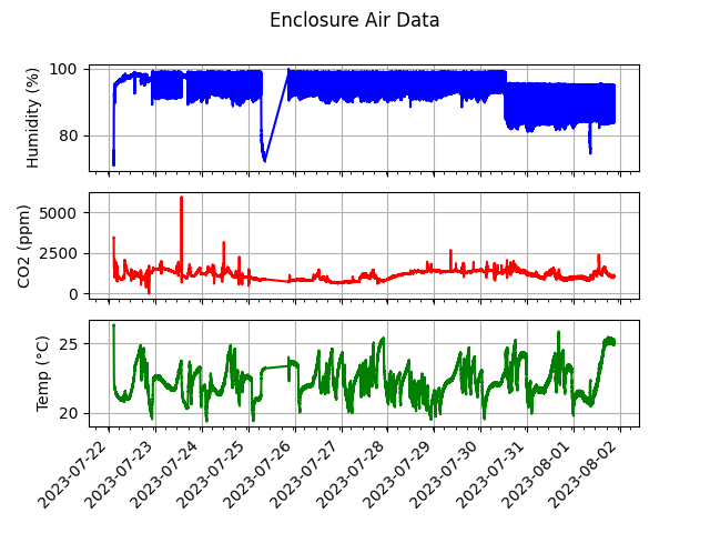
Following is a graph of all data recorded by the air sensor since the blue oyster mushroom fruiting block was deployed.
The graphs are generated programmatically using matplotlib. If you look at the humidity chart, you'll notice a drop to 75% before a diagonal line back to normal. This is when I forgot the fill the humidifier before bed, so it ran out of water at 6:35 that morning, but then 2 hours later the RPi power cycled and I failed to notice the service wasn't running for a full 12 hours. This was because the shift register doesn't reset its outputs during a loss of power, so the humidifier, fan, and light were on all day like normal, but never turned off.
The change in humidity on the 30th is when I changed the humidity profile to match the recommended min/max RH values provided by North Spore. And then, right before harvest, I let the humidifier run dry again. I'm not sure what the deal with the huge spikes in CO₂ were about. I doubt they really hit 6000 ppm on the 23rd, but who knows?
Currently all code on Github is copyrighted with all rights reserved. I'm sorry, this isn't really my style, as I prefer GNU or MIT licenses. However, until I really understand the implications of the licensing on the business, I'm going to err on the side of caution.
Problems and Improvements - A look at v2
It's not bad for a first attempt, but there is a lot of room for improvement. Overall, it was a huge success because it worked long enough to fruit the blue oysters.
Here is a list of things I'd like to change in the next version of the automated enclosure lid.
- Status LCD
- Buzzer alarm and problem detection code
- An always-on outlet for the relay box
- Better camera position, but also a fish-eye lens and full spectrum camera to see through the mist
- A way to prevent the SDC-30 from being exposed directly to the humidity without compromising its ability to read accurate data
- Move the humidifier inlet to the side of the lid and add an upward-facing elbow to avoid dripping and pooling of water (siphoned several gallons with a bendy straw through an exhaust hole over the course of fruiting)
- Add baffles to the FAE fan inlet to avoid localized lack of moisture. The mushrooms clearly preferred to be further from the fan.
- Write better sensor code to detect velocity of data points and account for delay in climate device effects. This will be especially important with a heating mat.
- Enclosure configuration profiles. Different mushrooms have different needs.
- HTTP API for data submission. Avoid needing a network drive.
- Branch out on microcontrollers - RPi has been very hard to find for a while. Considering Adafruit Metro M7 and Metro M4. Both are multicore chips with wifi.
- Tachometer and soil moisture level data