The workhorse of the automated enclosure is the relay switched outlet box. The concept is pretty simple. We want to use a Raspberry Pi or other microcontroller with GPIO pins to send a low-voltage signal to control a set of electrical outlets. Using this device, we can control up to 7 (or 8) outlets using 5v or maybe 3.3v input. This post will show you how I've built mine.
If you'd rather save yourself the hassle, just buy one of these instead. They are probably much better than the one we're making here.
This is the fourth one I've made. The first one, while it worked, was not very well done and ended up subtly shorting out. The relay board inside is pretty long, and because the first iteration of this box didn't have organized wiring, I just sort of shoved it all in there and screwed the outlets on. This bent the board itself, and because it was using the shortest standoffs in the kit, the back of the board came in contact with the box.
This wasn't a problem for a long time, until I built the second box and installed it on the shelf above. When the first box would kick a relay, it induced a charge in the second box, kicking relays randomly. I don't know if this was because the jumper cables weren't connected well, or what, but it was certainly very bizarre and stopped happening after I rewired the first box and found the bent board inside.
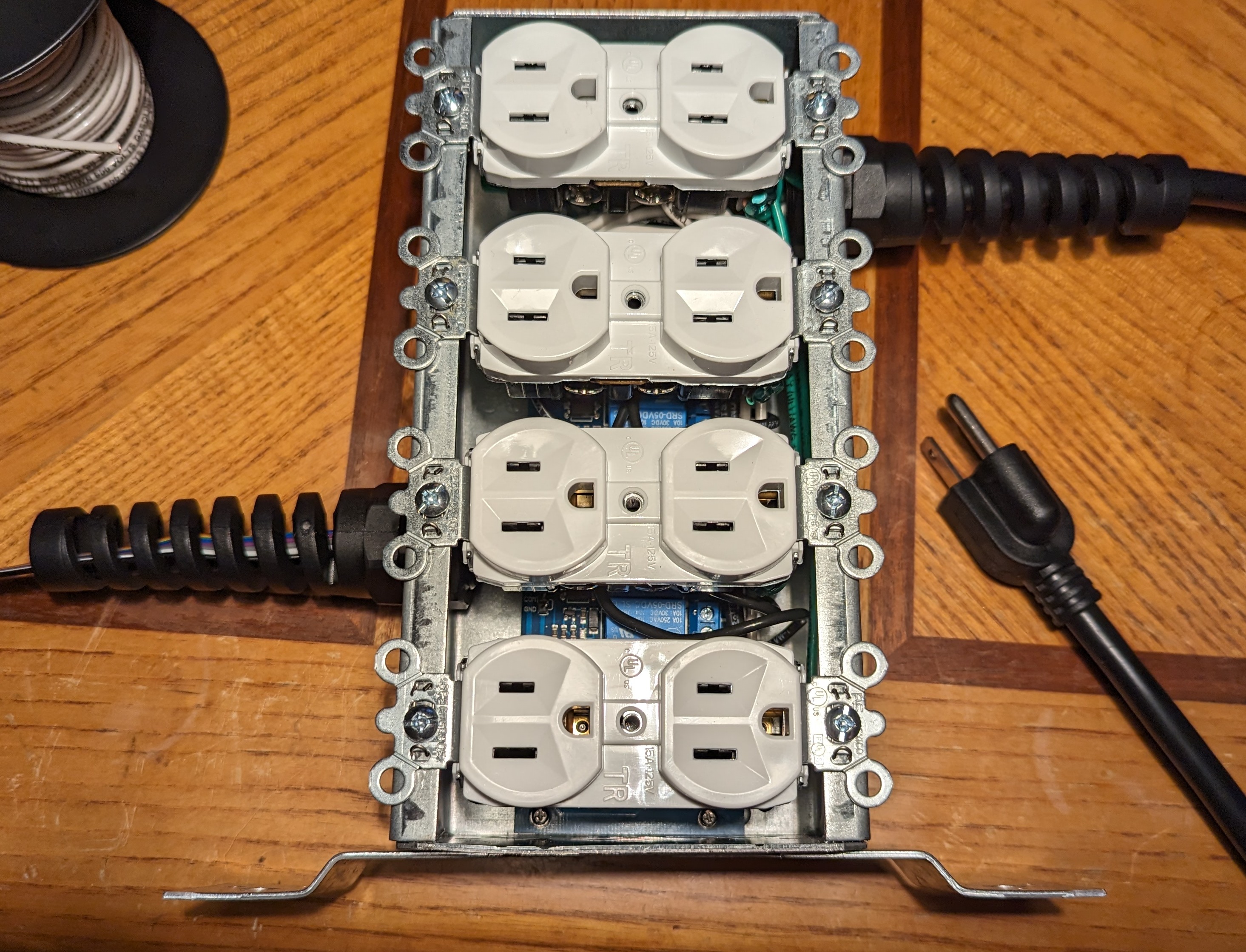
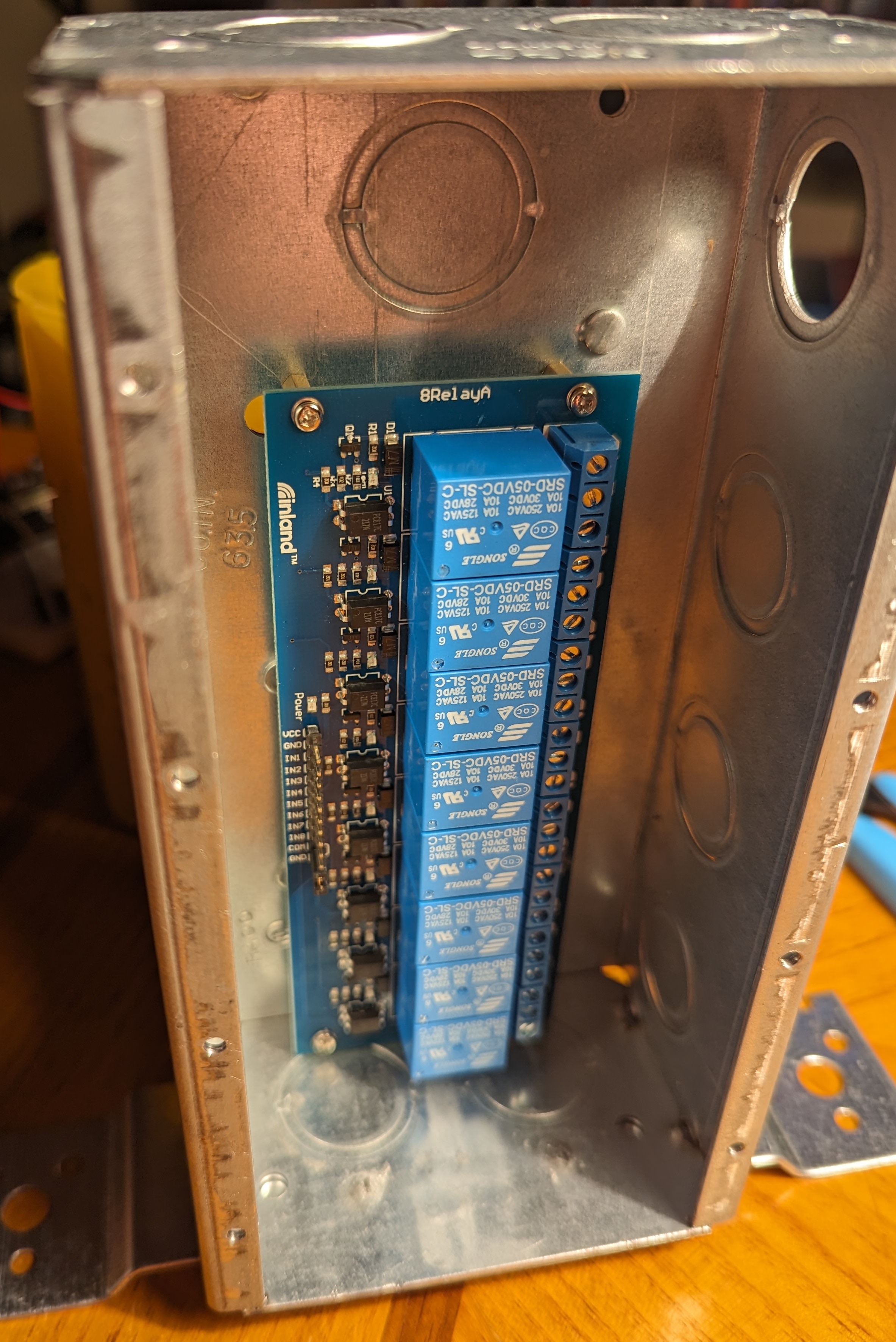
With clean wiring, there is plenty of room inside for everything, even the excessive use of wire nuts.
Drill and Tap Mounting Holes
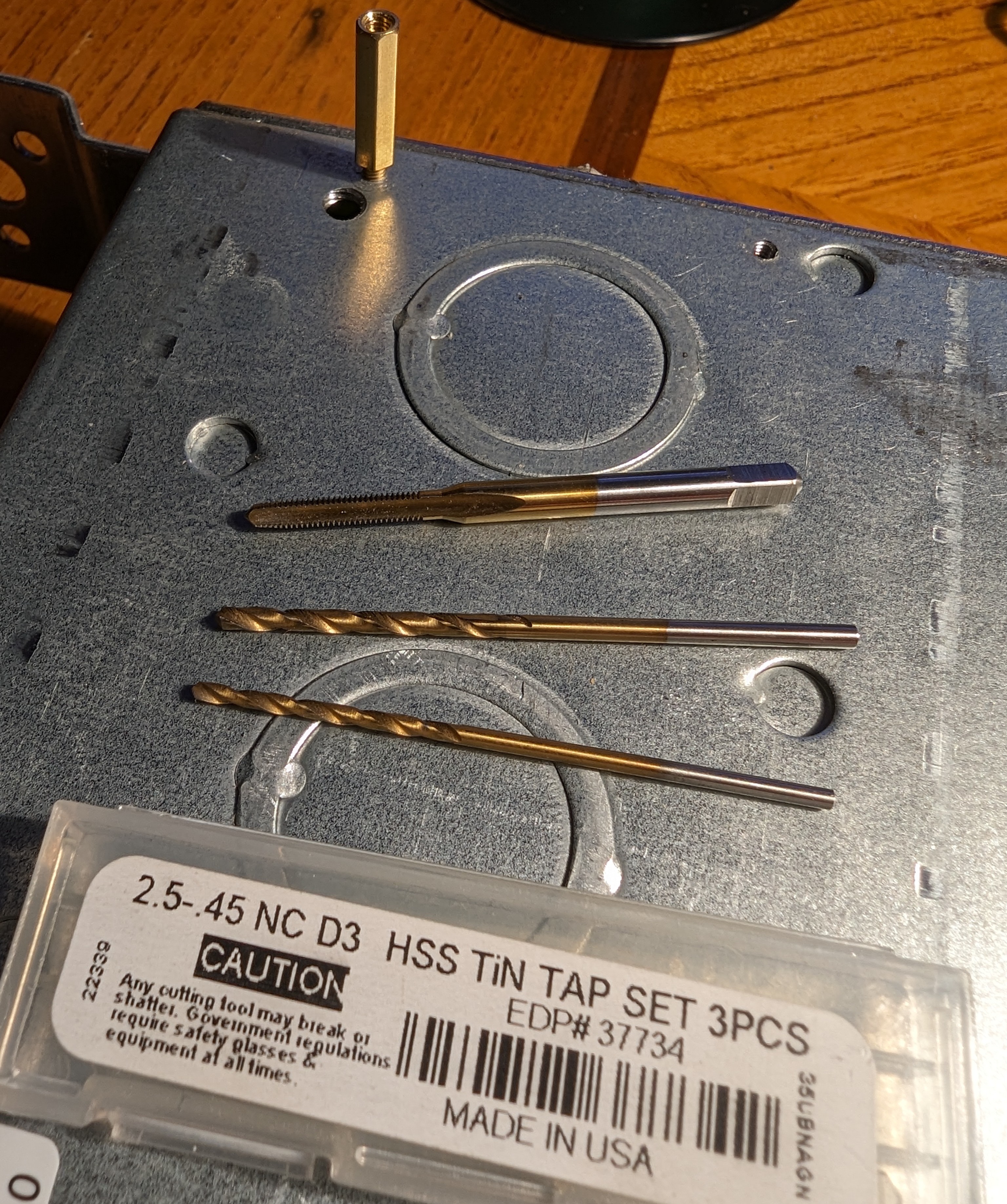
While building the enclosure, I wanted to mount boards directly onto the lid using brass standoffs that are commonly sold everywhere. Those standoffs turn out to be 2.5M with 0.45mm thread pitch. The taps for this size aren't sold at your typical hardware stores, so I found them at McMaster-Carr. They come in a set of 3, which is good, because I broke one on the third box. This is a great reason to wear safety glasses while tapping these holes.
Since I don't have a drill press or any friends with a machine shop, I very carefully used a power drill for this. On the first 2 or 3, the mounts didn't line up very well, so the boards are only held in by 3 screws. I think one might only have two. This final build went much better, and all four mounts lined up.
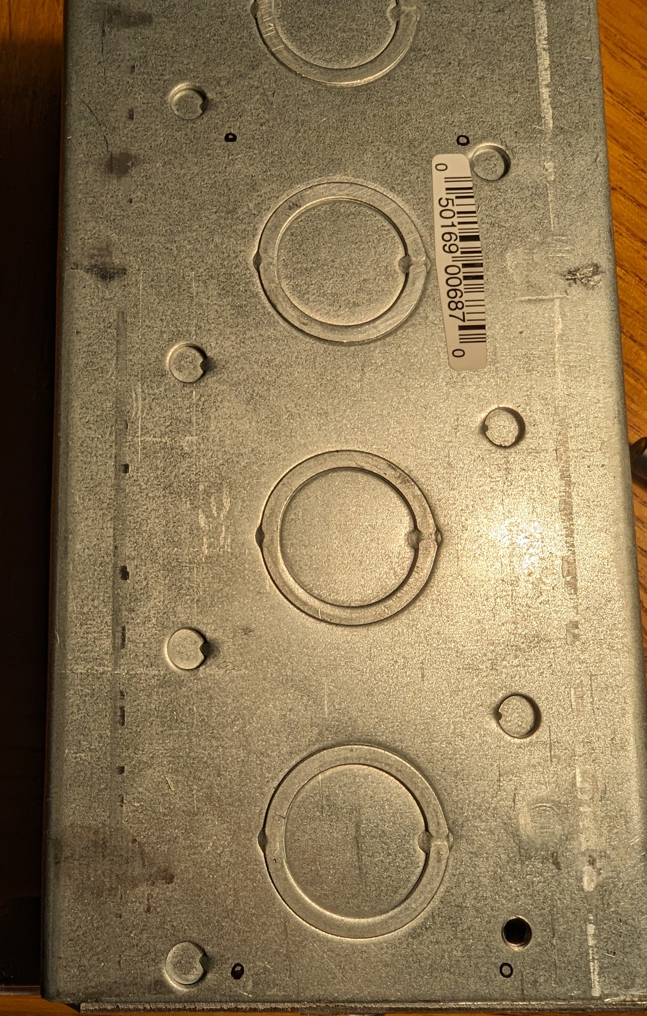
Start by placing the board on the back of the box. Maybe put it inside first to get an idea of the thickness of the walls, or just leave a little bit of room from the edge. It's also best to avoid drilling into any of the many punch-outs that exist in the box. I tried to go for the middle, because one side will have wiring and the other side will have the control jumper cabling, and both need a little room. The big gap at the top is where all the wire nuts (or "marrettes" if you're a Canuck) will be housed. It gets a little crowded there because that's also where the power comes into the box, so be sure to leave as much room as possible.
And if you look closely, you can see the black circles drawn onto the surface using a fine-point permanent marker.
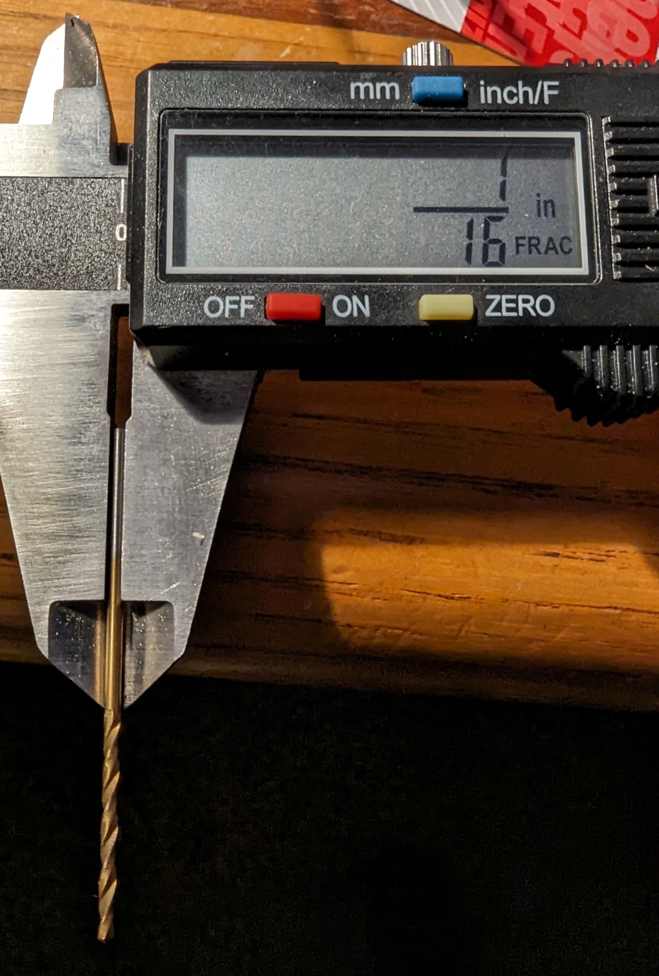
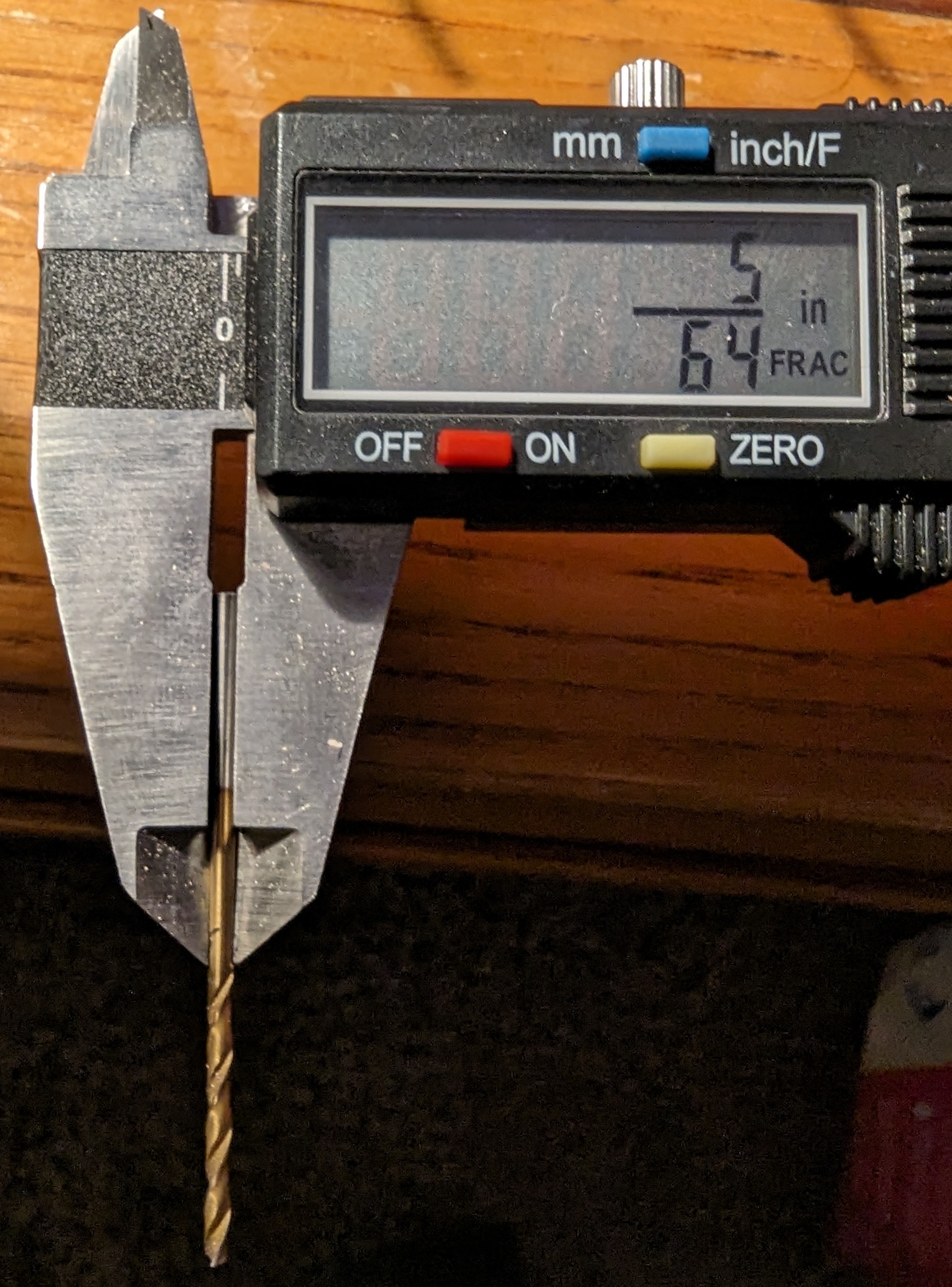
In order to actually get the drilling done, I painstakingly used the 1/16th drill bit to make a starting divot in the exact center of the markings. Once I had the center, I applied some pressure to bit before turning on the drill to ensure a guide for the bit so it didn't slip off. If you have a drill press, you probably won't have to worry about something like this.
I then used a slightly larger bit, a 5/64th to enlarge the holes before tapping them. A 3/32nd might have worked, but any larger and the taps won't have anything to carve into and your threads will be too shallow for solid grip.
NOTE: Using this tap is a little challenging. Unless you're Superman and can turn it with your fingers, you'll need leverage using a tap wrench like this. This is the correct solution because you always have full control of the turning. I didn't use one, and instead used the power drill. The drill has some momentum and I went past the end of the cutting threads, snapping the tap I was using.
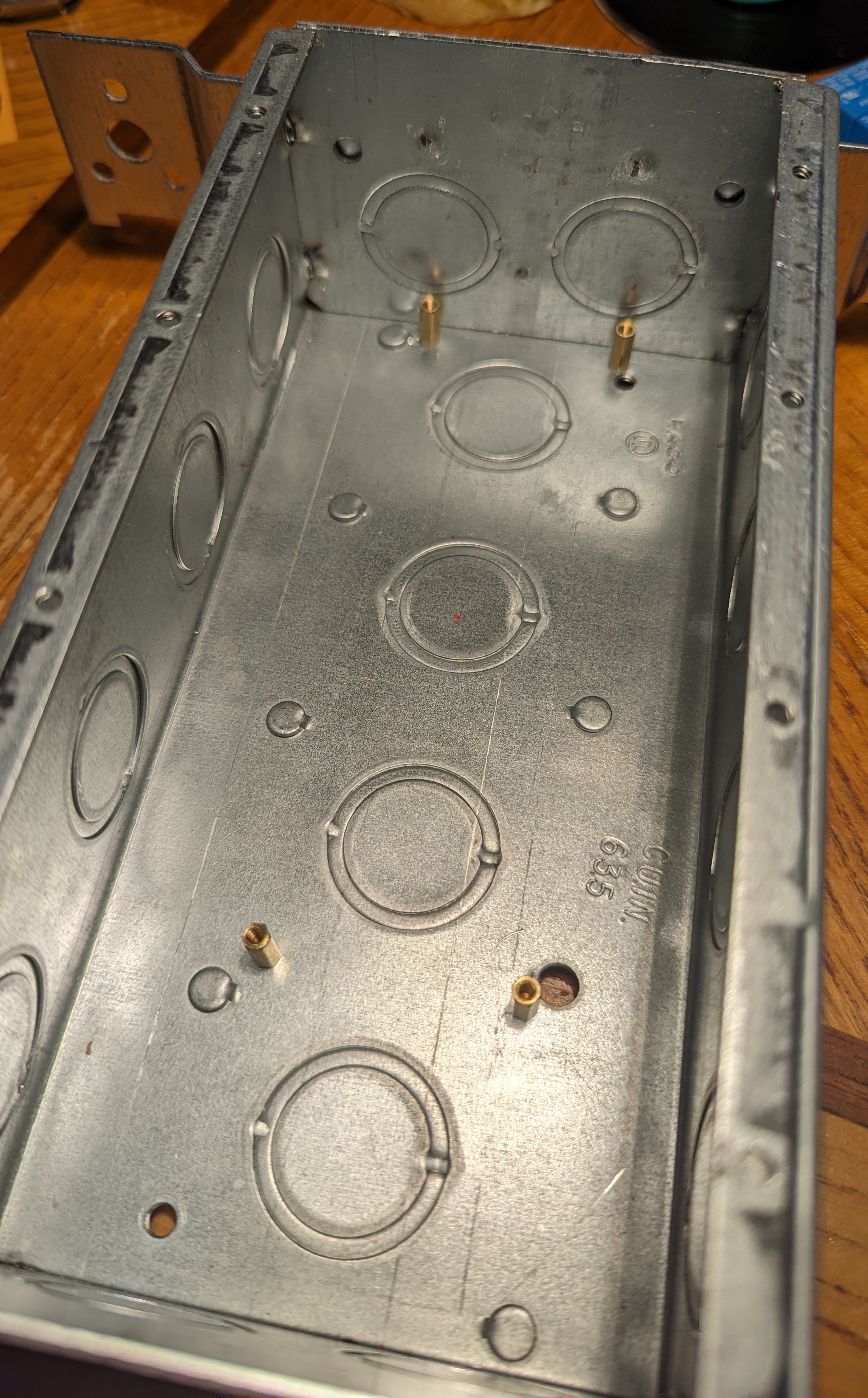
The two small holes at the top are the new ones made for this project, while the larger one is for a grounding screw. We're going to use the grounding hole at the other end of the box, so it's okay that this one is covered up by the board.
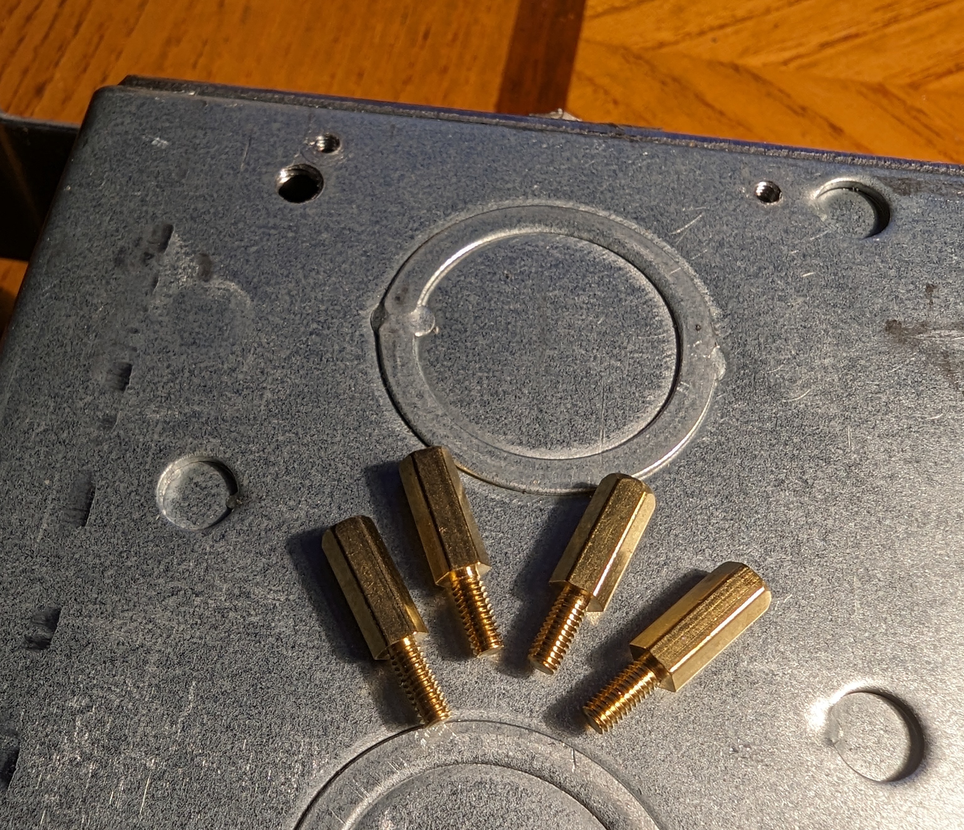
Here's a closer look at the standoffs being used. Notice they aren't the shortest ones that come in most kits, but the next size up. There's plenty of room inside the box and the back of the relay board has some pretty large traces and component terminals sticking out.
And finally we have the standoffs mounted. You might notice the punch-out hole removed next to the bottom-right mount. This was a little too close and would have interefered with the standoff mounting flush with the bottom of the box.
Now we can check to see if the board fits correctly. Honestly, it's a little late to do this now. Drilling another set of holes is not ideal, but you can if you have to.
Prepping the Outlets
The outlets being used here, and all modern outlets as far as I know, have a jumper between the two plugs that can be removed. In my office, I used this to keep the bottom half of the outlet on all the time, while allowing the top half to be controlled by a light switch. For our purposes, it will let us control each recepticle individually instead of turning on two at a time.
!Wear safety goggles! Breaking these tabs off leaves a good chance of hitting yourself in the eye. Don't take any chances.
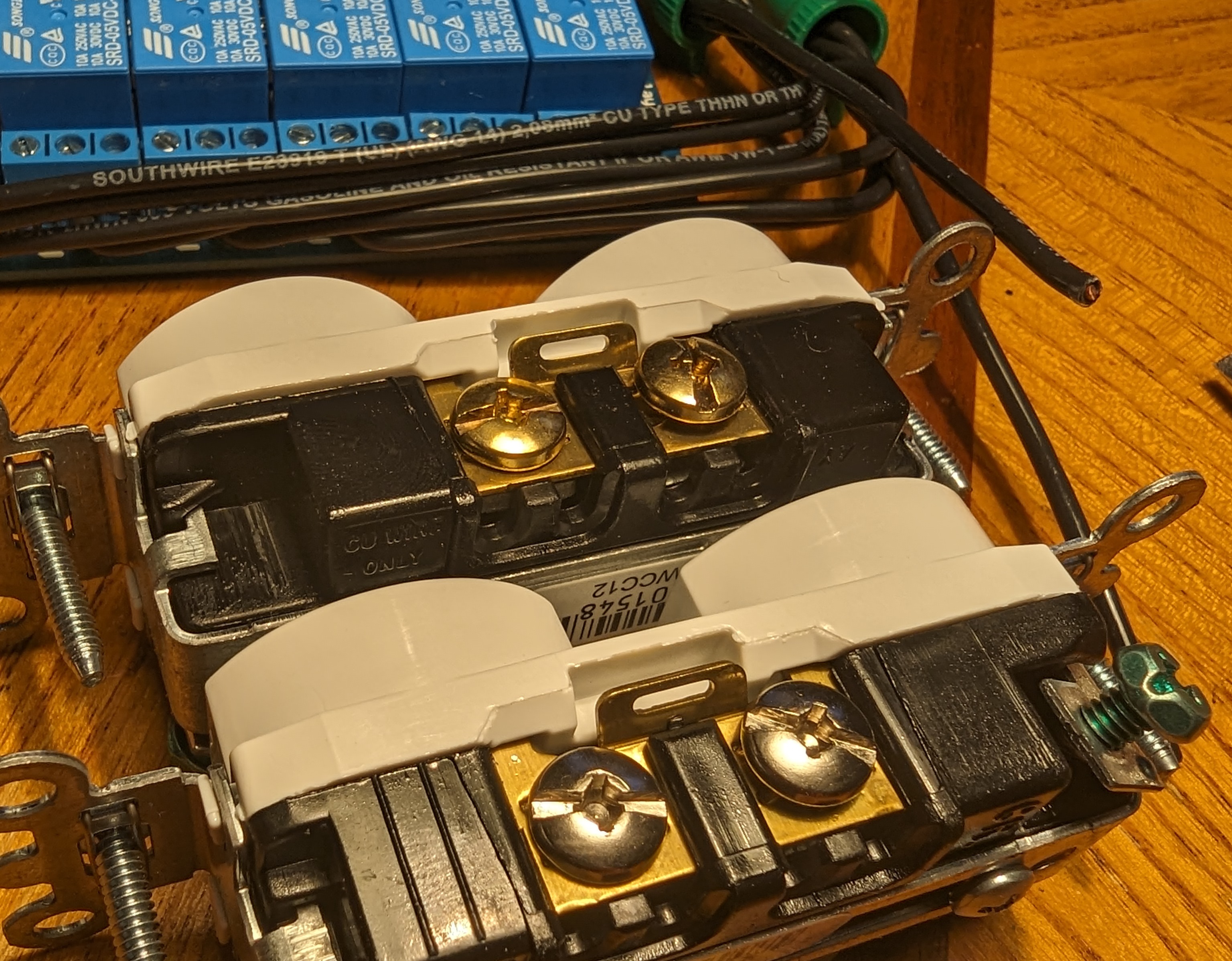
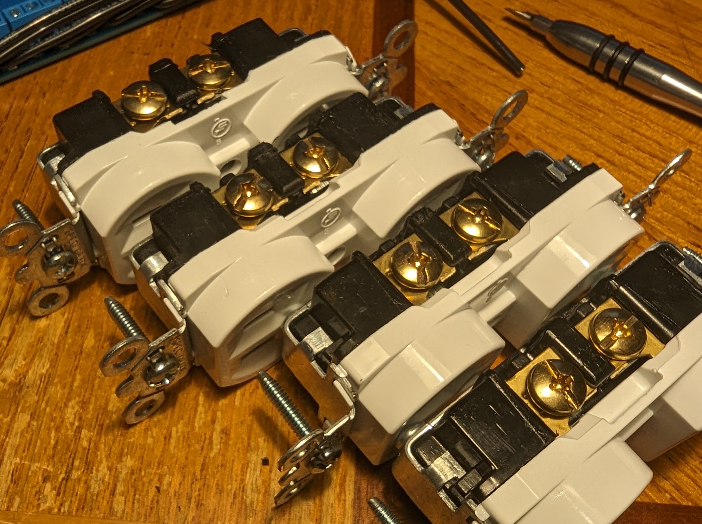
First thing to do is identify the difference in contact screws on your outlet. One side is intended to be "hot" while the other is "common" or negative. We want to break off the jumper tab on the hot side. The picture below shows the difference in screw colors. The one on top has a brass colored screw, while the bottom one is silver or white. Don't break the tab off on the silver side, or else you'll need double the common wires.
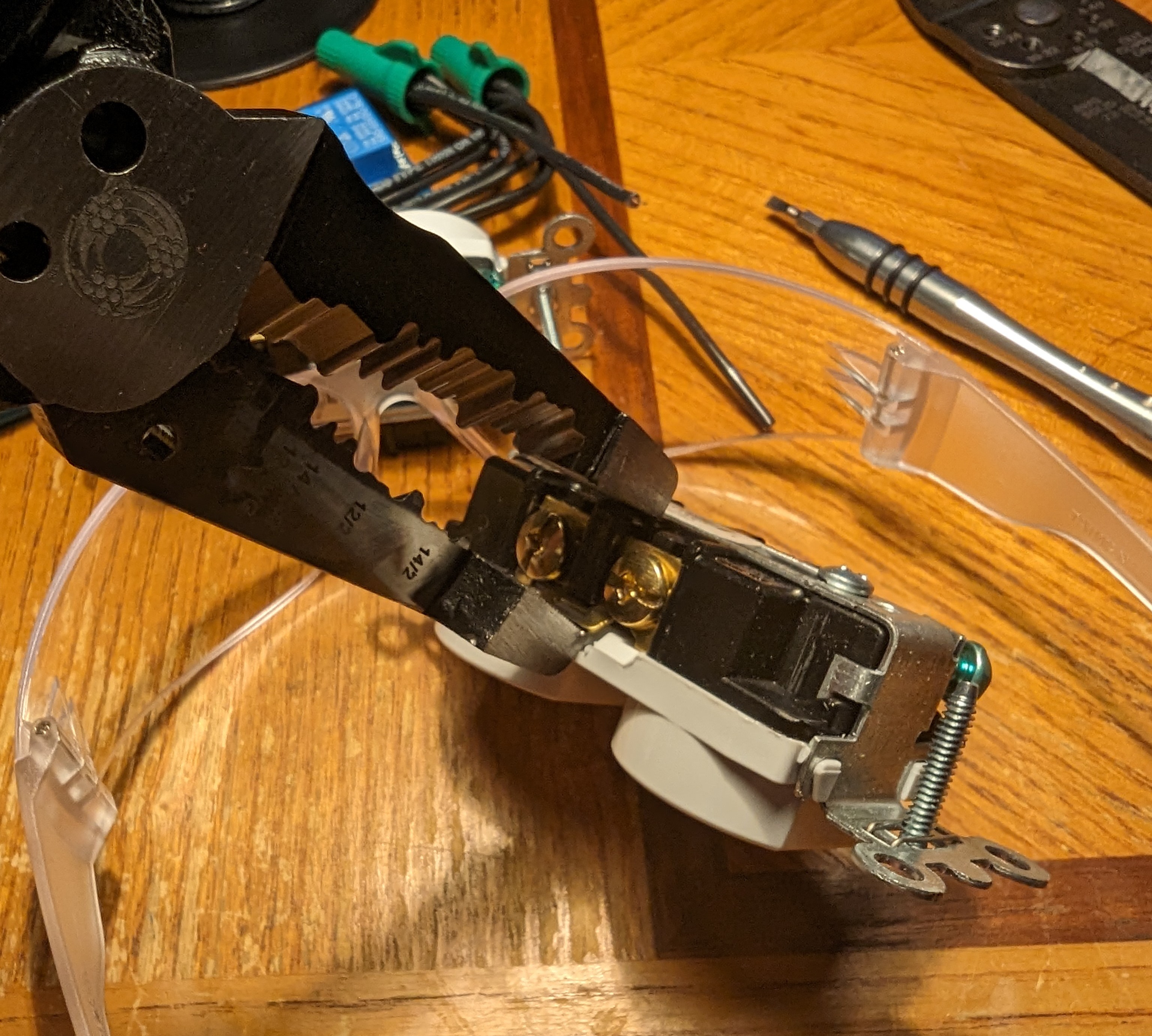
I don't know the official way of doing this, but I've tried using a flathead screwdriver to bend the tab back and forth until it fails. This method worked about 50% of the time for me, leaving the jumper intact the other times. The following method works every time but requires a greater amount of force, and has a chance that the tool slips. Use a strong set of pliers for this. I bet a cheap set of needle-nose would break.
!Keep your fingers clear!
Here's the resulting cleanly broken tab, followed by all four completed outlets.
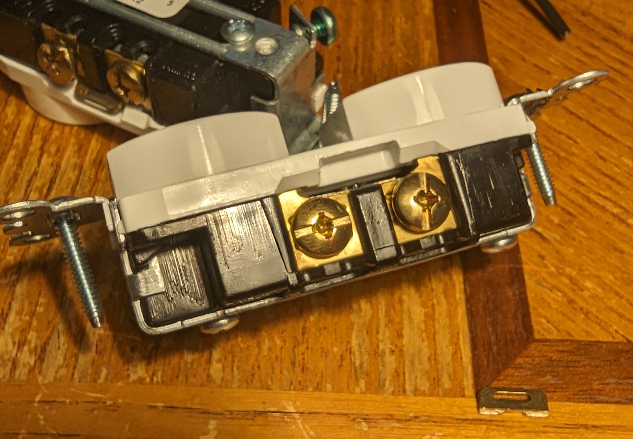
Now we're ready to proceed.
Internal Wiring
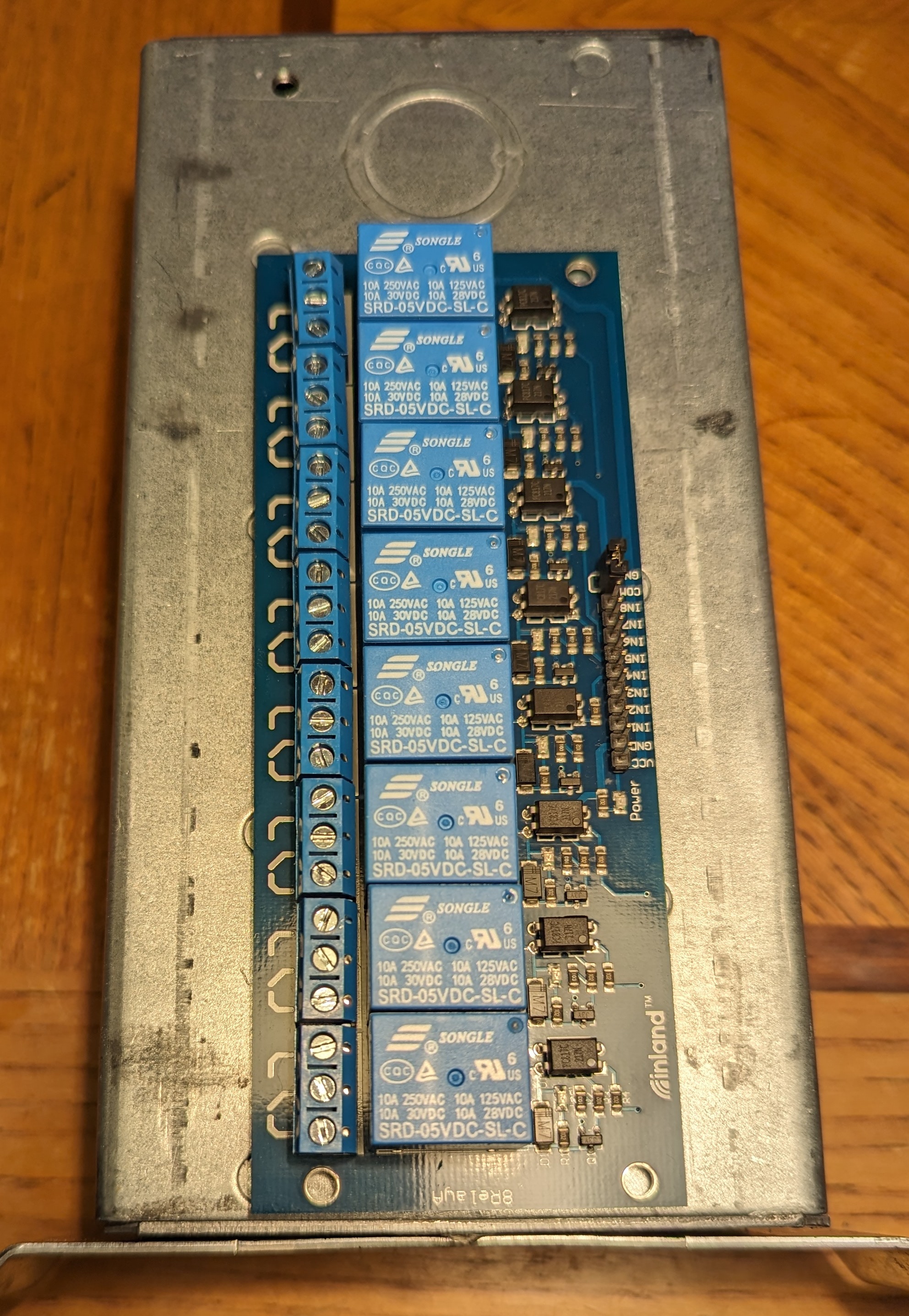
With the mounting holes out of the way, now we can start wiring our board. Each relay has three terminals. Using 14g solid wire, we need to run our power from the wall into the middle contact. This is the terminal that is being switched. The terminal on the right is the normally-connected, or "NC" terminal. This one stays empty. I like to screw this one down all the way to remind myself not to put anything in it. The first box I assembled, I wired a white common wire into each one. Well, since it's normally closed, I immediately blew a breaker when I plugged it in. The NC terminal is for supplying power to a circuit when the gate isn't activated, and since we're not powering anything in this state, we leave it empty.
To better understand relays, check out the Adafruit relay feather tutorial or the similar SparkFun product.
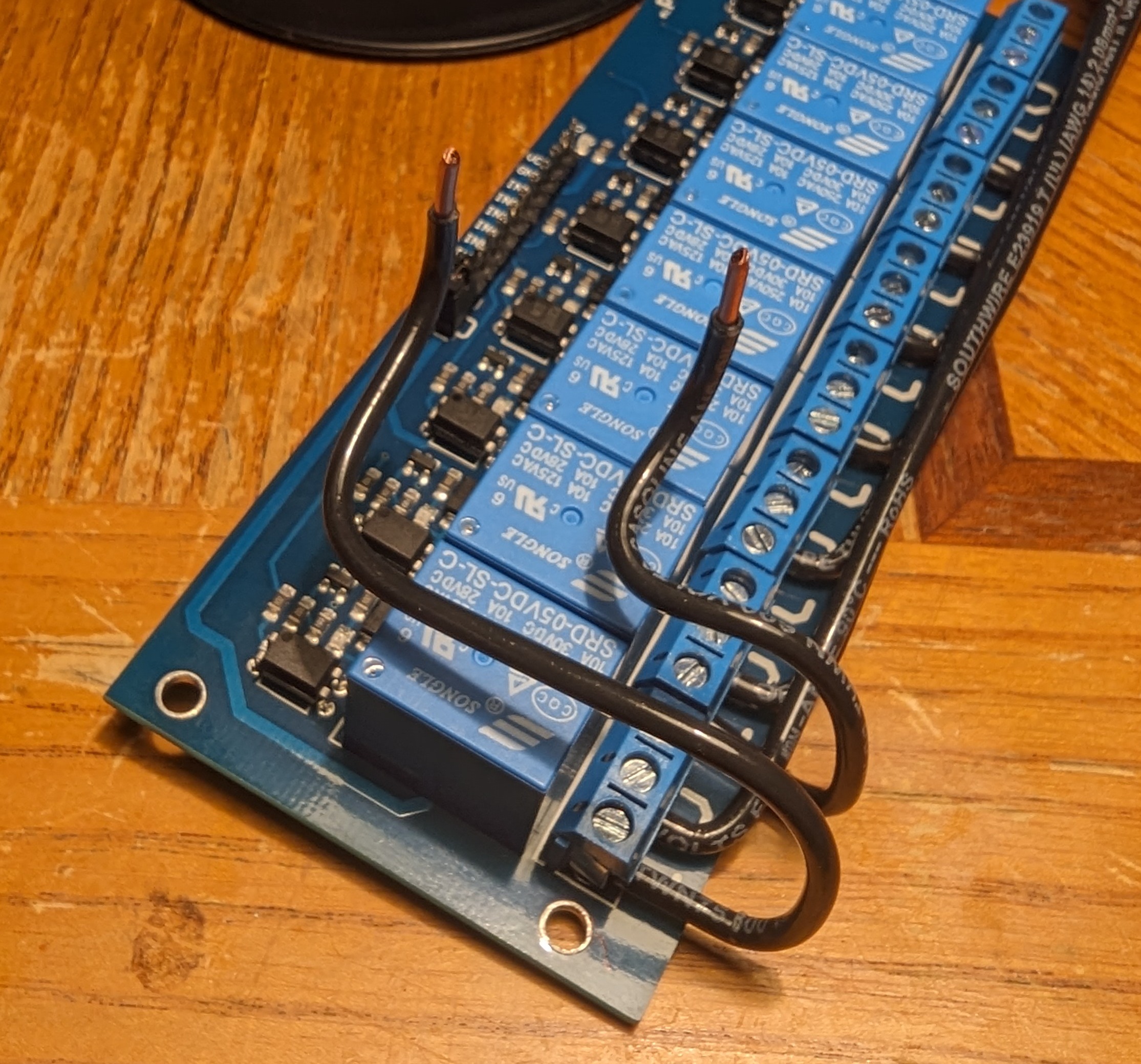
The first thing to do is run our live supply wires. Be sure to do this neatly, as there is going to be sort of a lot going on in this box by the time we're done.
CHOOSE NOW: The version I'm making here doesn't use the 8th relay. Instead this outlet is always on in order to power the Raspberry Pi or microcontroller. If you don't want an always-on outlet, add a supply wire to the last relay and wire it just like the rest. Otherwise, you'll wire this outlet directly to the hot supply, as shown later.
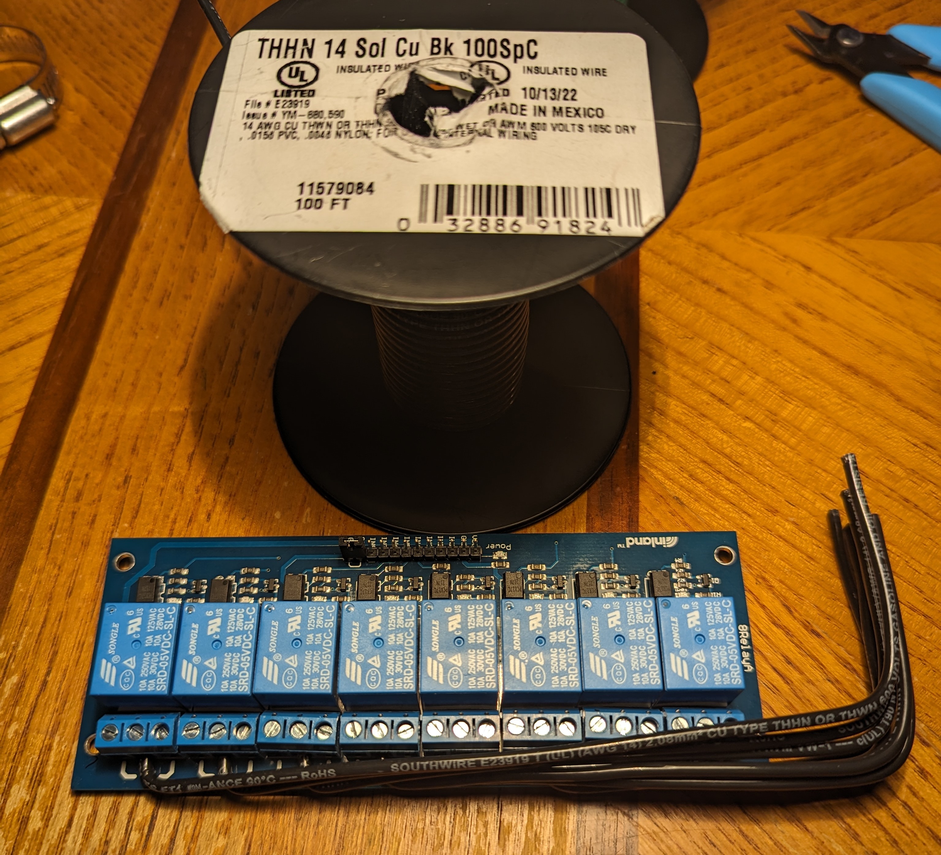
You'll probably need to split these into two groups, as it would take a very large wire connector to fit eight or nine 14g solid wires into one. The two wires extending past the bottom of the image are the pigtails that will be connected to our supply.
Next, we'll be positioning the outlets. Some things to consider: you might want to take an outlet out to get a better view, or to replace it. During assembly, the outlets need will be at their furthest distance from the board, when you start screwing them into the J-box. The wires need to be long enough to accomodate this, but also need to be arranged neatly when everything is assembled.
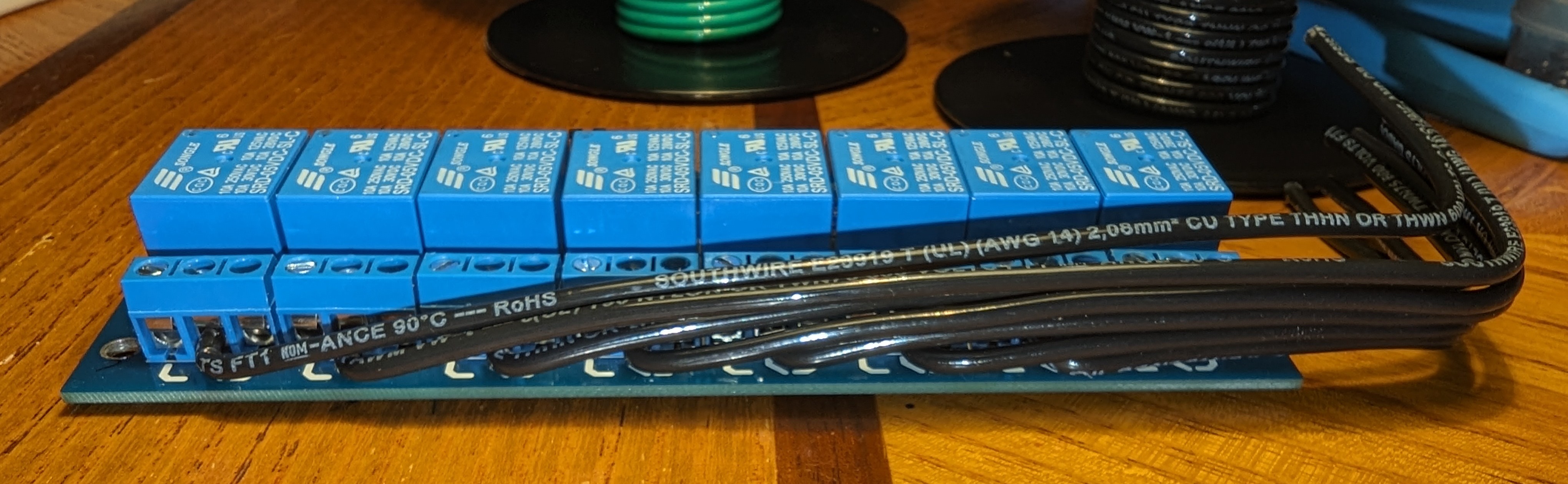
As a result, the live wires to each outlet should behave a bit like a spring, as shown below. With an outlet attached, it will be able to move a useful amount in all three dimensions.
The outlets used here can be wired straight into the back of the terminal instead of using a hooked wire directly under the screw. This makes things a bit easier to manage, so we've done it that way here.
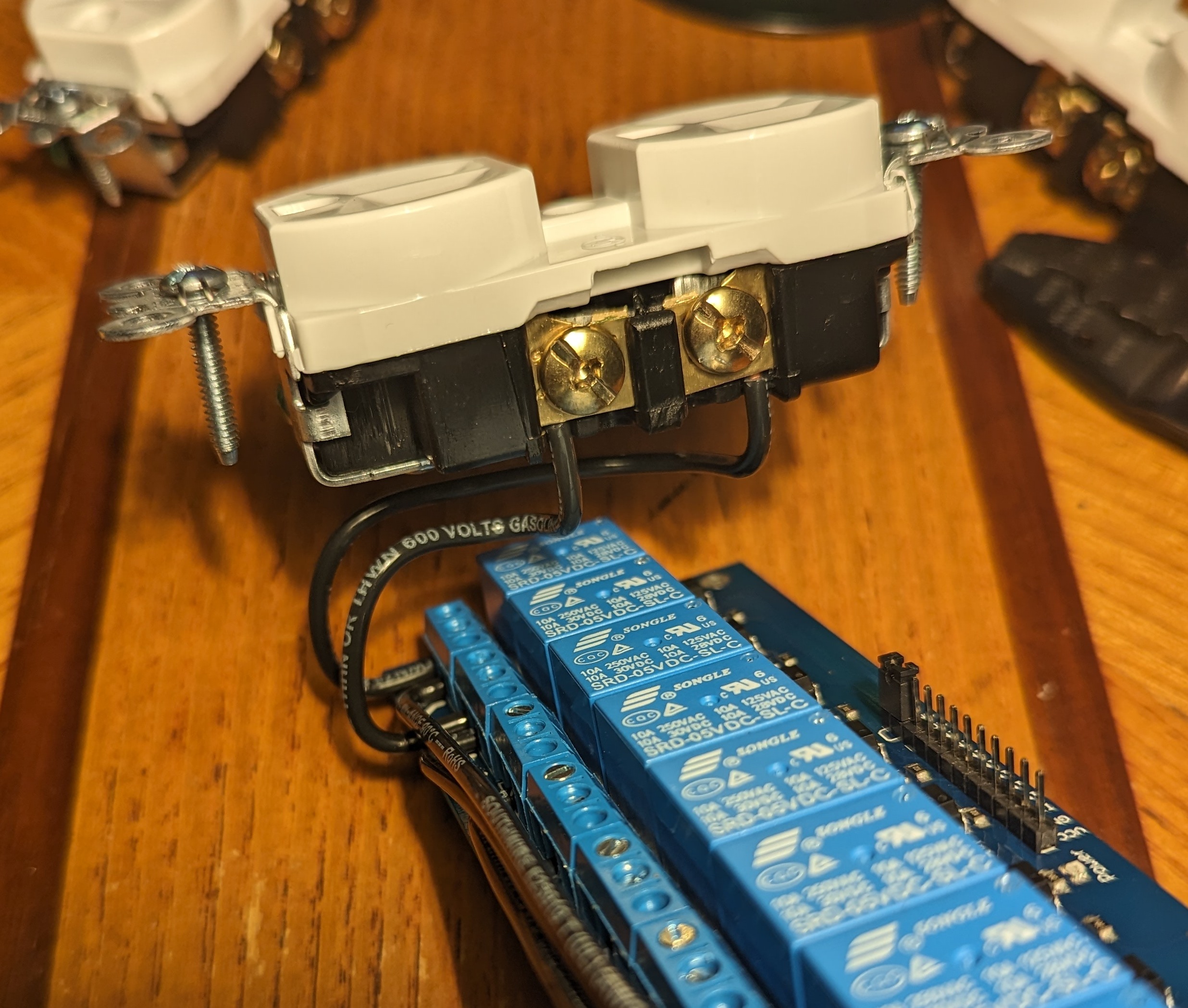
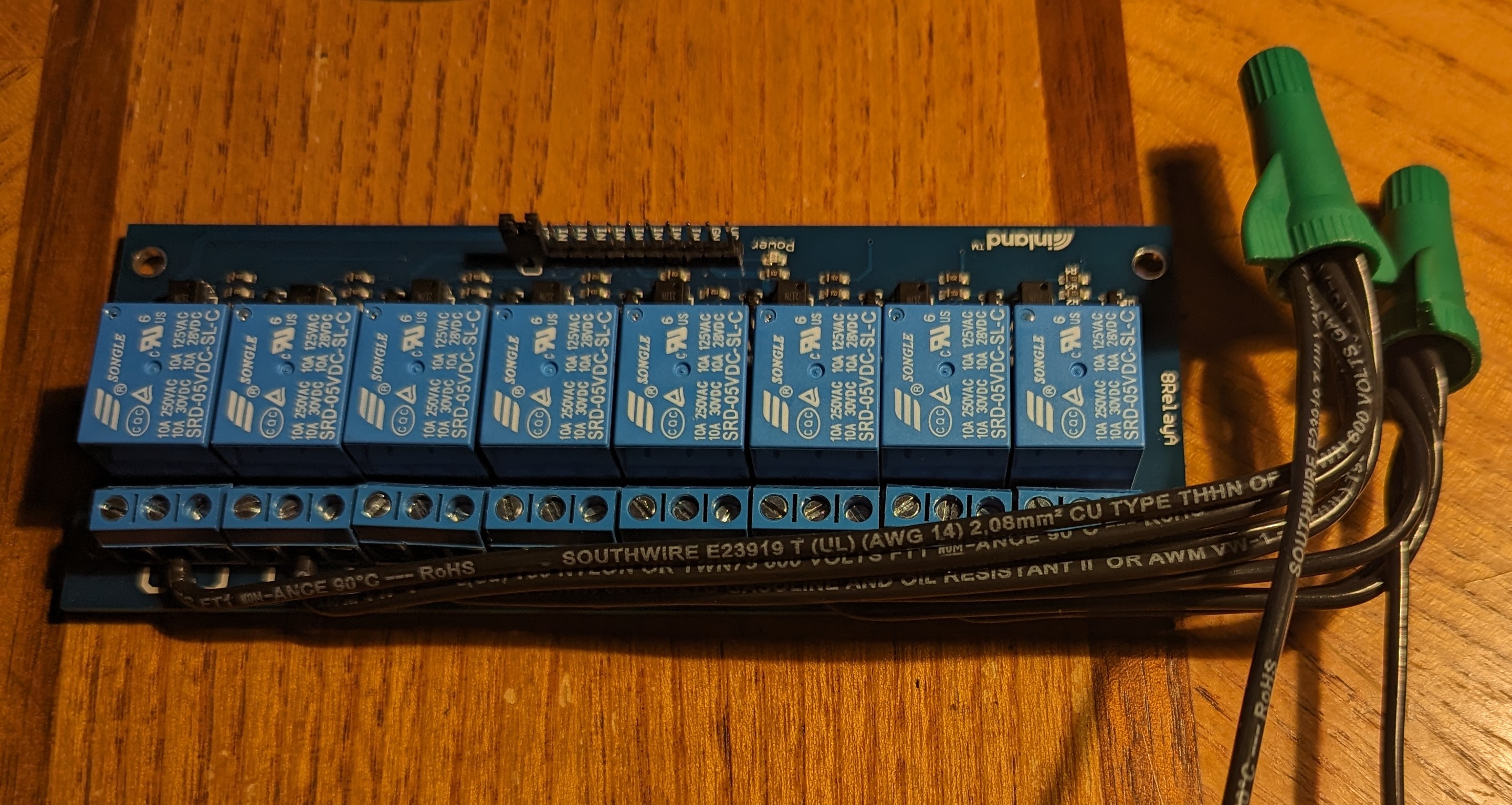
The next image shows all four outlets connected to their springy live wires. You'll notice on the right, the visible wire coming out of the terminal heading directly to the supply wires. This is the outlet that will always be turned on. Again, if you prefer to have all wires controlled by the relay board, connect this wire to the 8th relay instead.
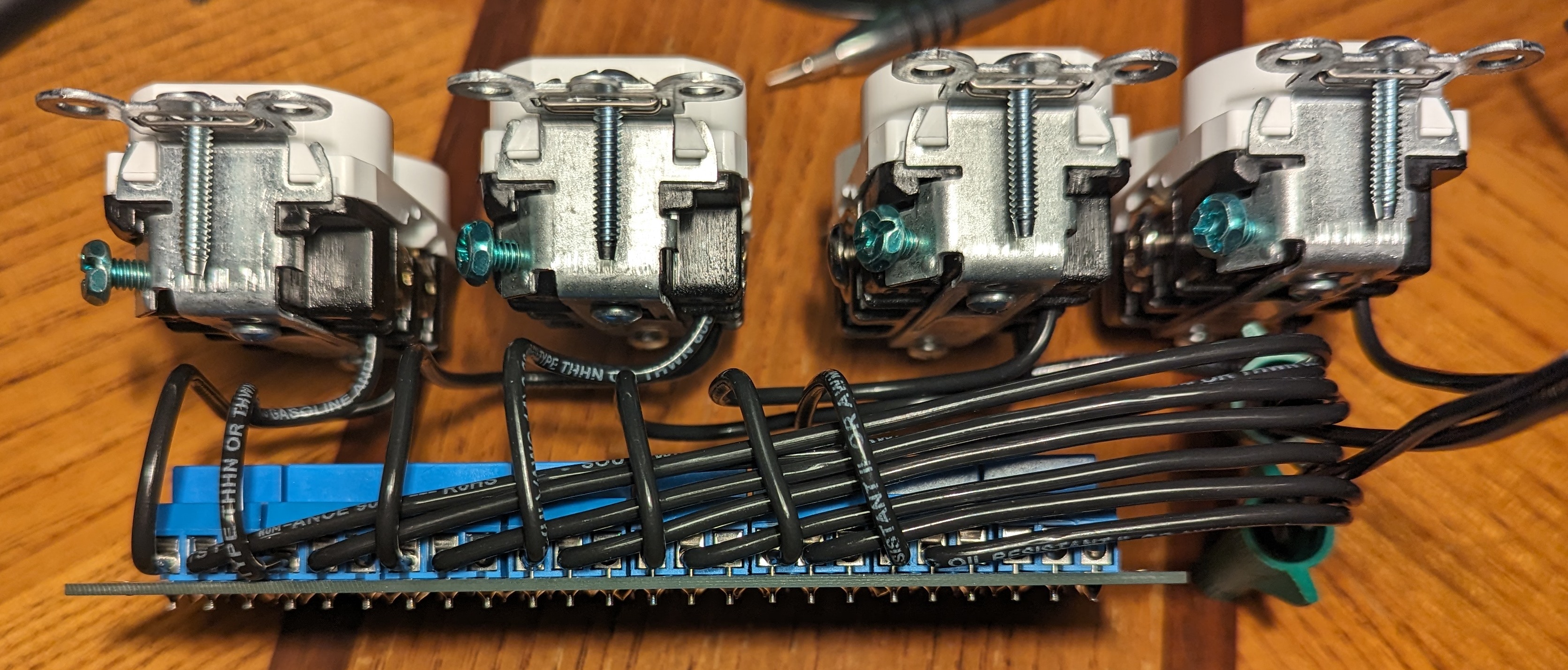
Next we'll add the common wires. We only need 4 total because the jumper tab on the silver side of the outlet was left intact. Otherwise, we'd need to add a common wire to all 8 silver screws.
It's not the best picture, but you can see the white wires running neatly along with the supply and switching wires. They are connected between the third and fourth outlets.

Now we'll add a grounding wire to each outlet, and tie them together on the right.
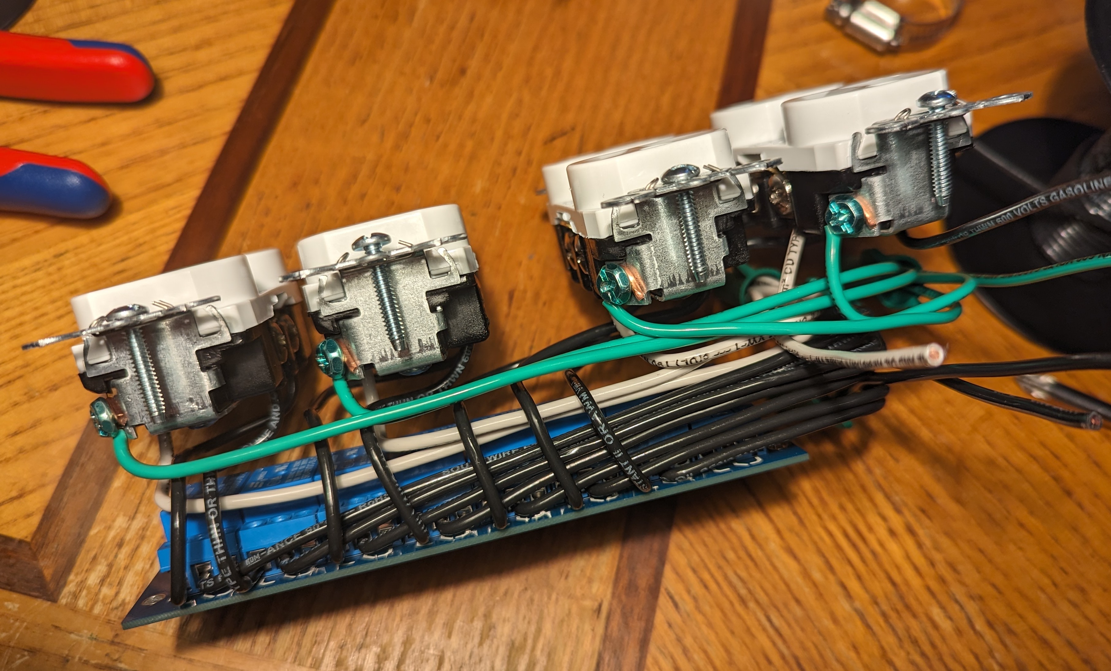
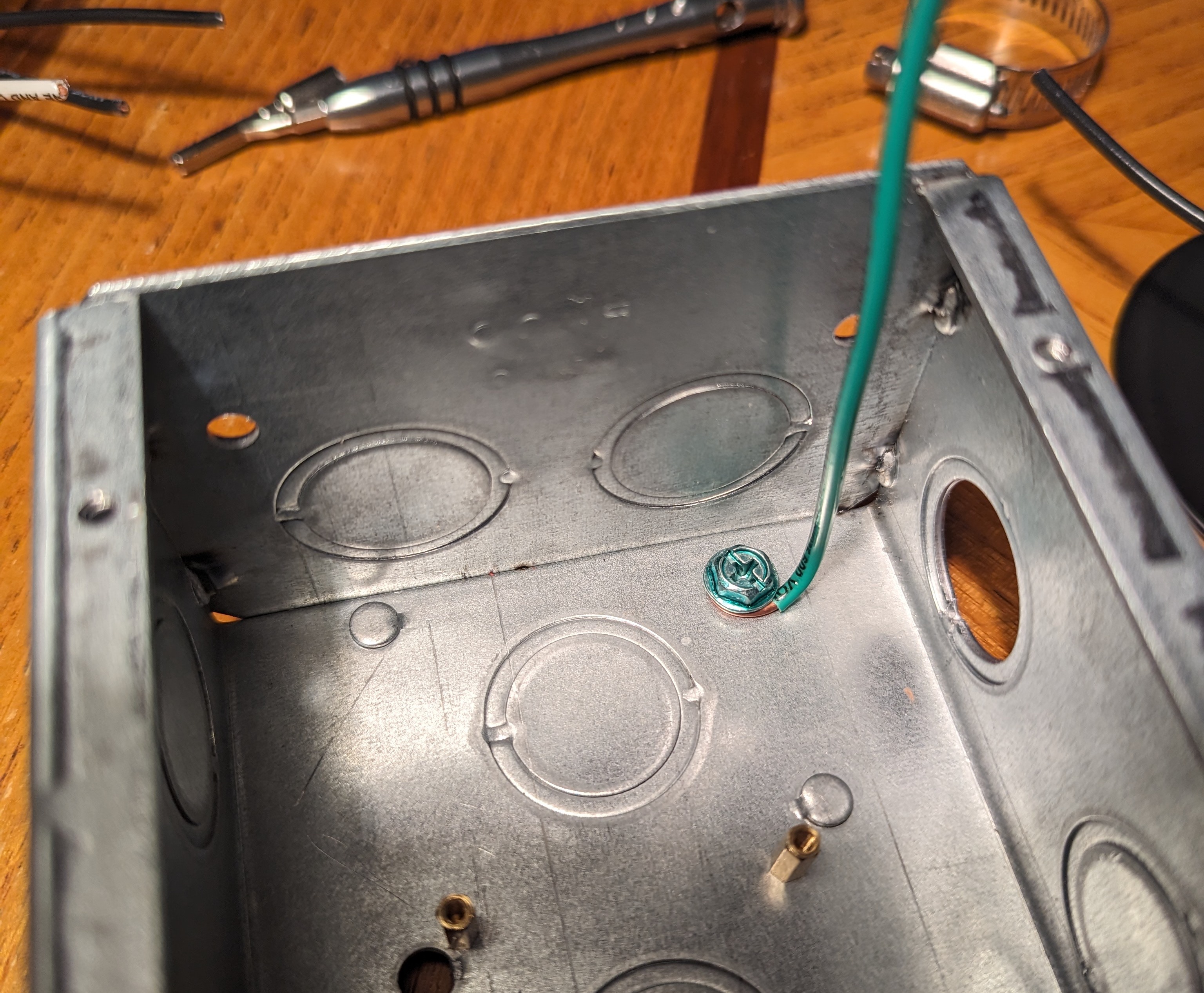
This is a good time to go ahead and add the ground for the J-box itself. This threaded hole was added to the box during manufacturing, and the wire is secured using a grounding screw, sold separately.
Final Assembly
If you haven't already, go ahead and knock out the holes where you'll need them. The box I have has a hole directly in front of the control pins for the relay board, and also at the top for the power cord.
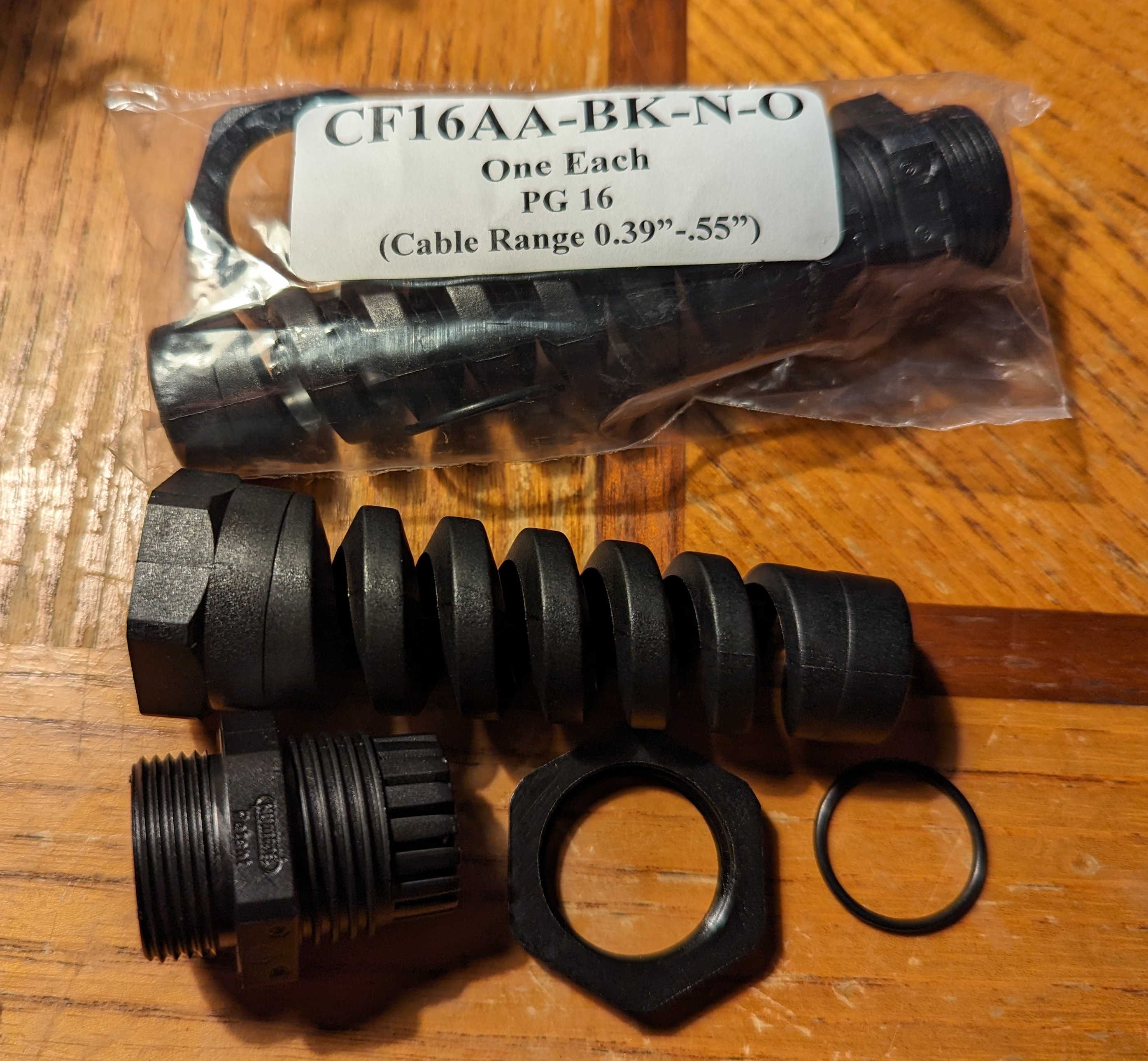
Add the flexible cord grips to the knockouts now. They don't have to be fancy like this, but preventing the wiring from contact directly with the rough edges of the hole is crucial. Instead, something like this might also work.
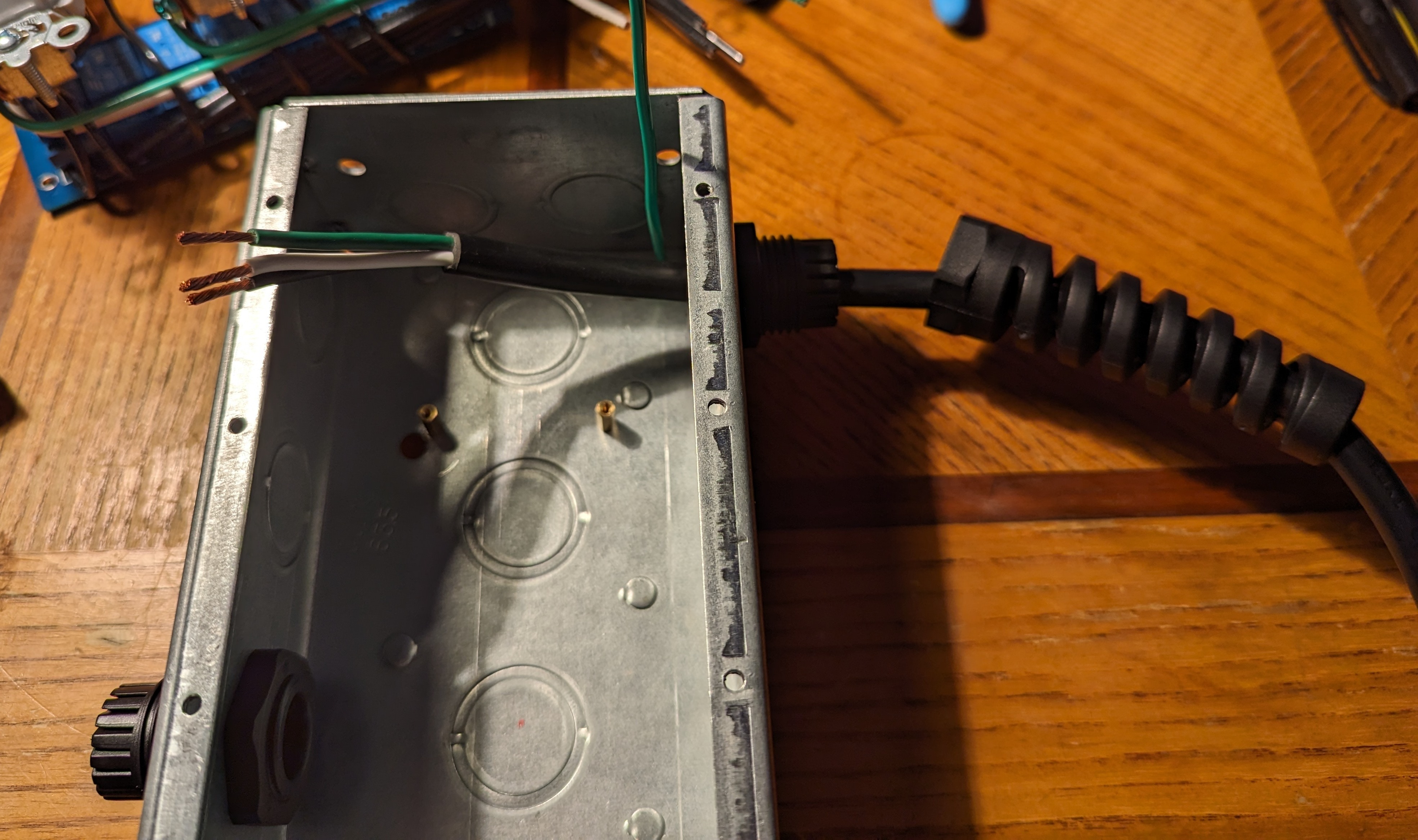
Here you can see the power supply cable, which came with the wires already exposed, purpose built for this type of project. You can of course cannibalize one you probably have laying around already.
Don't forget to thread your wiring through the flexible portion of the cord grip before connecting the wires!
After connecting the pigtails to the power supply, and the control wire jumpers to the relay board, you're ready to very gently shove everything into the box and screw the relay board to its mounts. This is genuinely the most challenging part of this whole project, so go slow and be patient. You don't want to damage any of the wiring or disconnect anything in haste.
Gently pull the excess wire out of the knockout holes for the control and supply cords.
This is the control wiring after assembly.
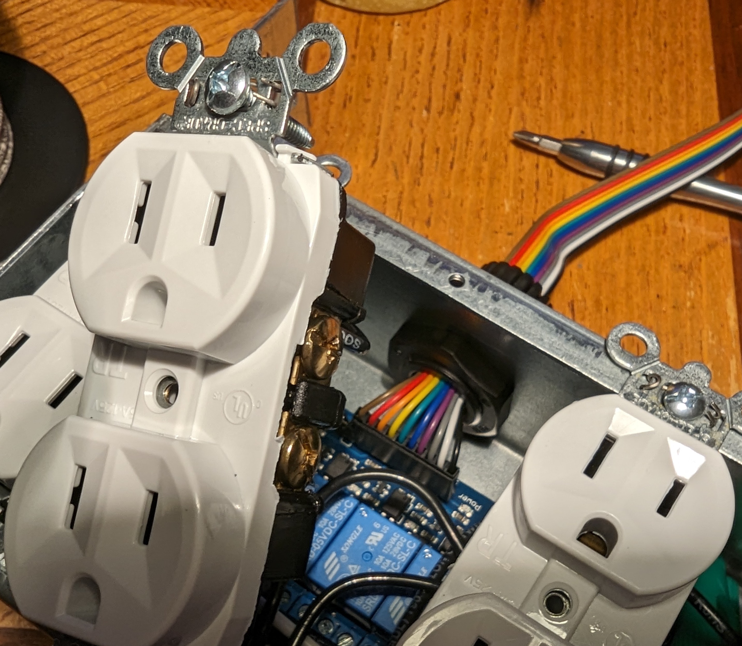
Finish assembling the cord flex grips, screw the outlets to the j-box, and if everything went well, it should look like this.
Warnings
Take caution when plugging this into a live outlet for the first time. Use an electrical test kit to ensure the device you have built is safe. The linked kit has a no-contact wand, a multimeter, and a light-up plug that will ensure you've wired it all correctly.
Stay safe!