One of the data points I wanted to include in the first version of the automated enclosure was the fan speed. Ultimately it's sort of a worthless data point so I didn't end up getting it to work before using the enclosure, but now I've had some time to circle back and would like to record my findings.
This time around, I didn't even bother to use a Raspberry Pi. I just wanted to see if I could use more basic means of understanding this admittedly very simple circuit. In the enclosure post, I linked to this StackOverflow Electronics answer which described a safe circuit that I attempted to implement. It may have even been working, and I just didn't realize it. We'll dig into that more later. First let's find out how this thing works.
Armed with the following results (and tools), I am confident that we can get a working data source at ~75Hz in a Raspberry Pi python script. This RPi sampling benchmark puts capabilities between 5 and 20 kHz, depending on what library is being used. The fan tachometer input should pose no problem at all.
Experiment 1
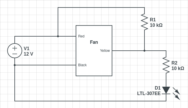
I hope the following two images are representative of each other. I had to screen grab the Circuit Lab image because they wanted $80 a year to export a PNG. Yeah, maybe next time.
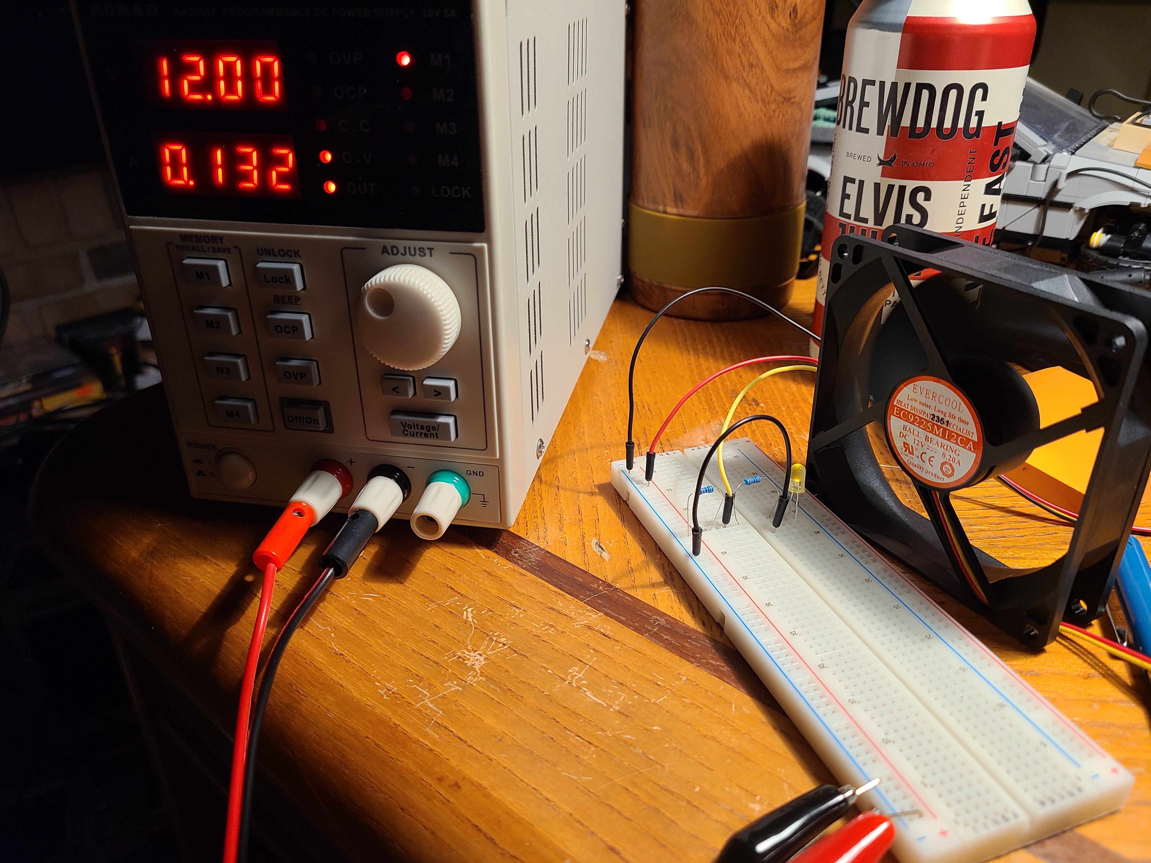
The objective here was to create a simple LED circuit to see if it would blink with the output of the tachometer. These images are what ended up working successfully.
First I set the power supply to 12V and 0.20A because that's what it says on the fan. However, when running, the current drawn never gets beyond 0.14A, preferring to sit at 0.133A.
For those that aren't aware, there is a hall effect sensor in the fan. According to the referenced SO answer, the signal is high from the tach wire, and low when the hall sensor is engaged. This called "open drain" or "open-collector". According to Wikipedia:
output is pulled Low when the MOSFET is conducting
When attempting to get some kind of reading with my multimeter, the voltages never gave any real reading. They were the same voltages I might get if I held both probes between my fingers, in the neighborhood of 20-30mV. This was suspiciously low, to the point where I didn't think it was working, but the fluctuating values gave me hope.
It was at this moment that the concept of a "pull-up resistor" finally clicked in my brain. I needed to pull the signal voltage up to something readable by putting a 10kΩ at R1 in the diagram. This brought the potential up to around 6V on the tach signal pin (yellow). This voltage is too high for both a RPi GPIO pin (3.3V) and an LED (2.2v), so I added another 10kΩ resistor at R2 to conserve the LED's magic blue smoke.
At first, I didn't think it was working, but then I slowed the fan with my finger, and low and behold, the LED turned off.
As a side note, the drop in current is around 0.07 amps. With the power supply reading about 0.13A, I measured 0.04A across the +/- terminals of the breadboard, a drop in current of about 0.07A. If I'm doing the power formula correctly, that's 0.84 watts and a resistance of about 170Ω across the fan. Physics was many years ago, I have no idea if I'm doing that right.
Anyway, the last thing I did was connect my new oscilloscope probe to the tach wire to see what it looked like.
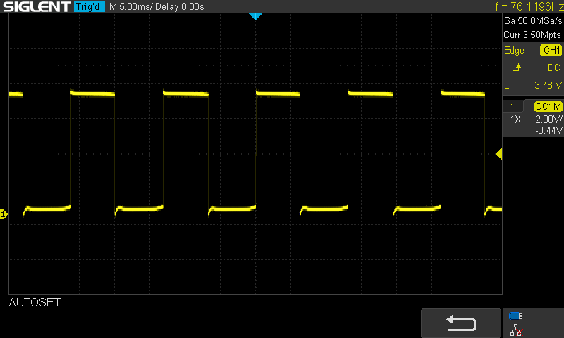
I'm not sure I'm reading this correctly, but it looks like the signal potential is 3.48V. This is still a bit more than I'd want to send to a GPIO pin, so I measured on the other side of R2, and the value was closer to 1V.
Another note. These fans pulse their hall effect sensor twice per rotation. In the top-right of the scope output above, you can see the frequency at about 76Hz, which is 4560 rpm. The stated speed according to the manufacturer, however, is 2000 rpm, so we can be pretty sure we're getting 2 pulses per rotation.
Experiment 2
Without using a pull-up resistor, I connected the oscilloscope probe directly to the tachometer pin just to see what's happening. It's absolute chaos is what it is.
I have seen the frequency as low as 12Hz and as high as 30kHz. The voltage is tiny, between 20mV and 120mV. Completely useless. You definitely need that pull-up resistor for nice clean voltage readings.