This is a post about mistakes. I made about as many of them as possible without having to buy another piece of plywood. The final product is a working 24"x48" laminar flow hood. I didn't write this during the build, and I didn't keep any notes, so I'm sorry for any details I may have forgotten in the past couple of weeks since the build was completed.
The first mistake I made was trying to follow someone else's instructions without paying attention to what I had actually purchased.
Actually, the first mistake I made, honestly, was probably trying to build this myself. I spent a lot more than I would have if I had just purchased one.
Instead, I bought a 24"x48" HEPA filter, and a giant blower fan with the mounting bracket to go with it. The shipping for these items alone was just shy of $300. I probably could have gotten a much better deal if I had taken a bit more time and sourced locally. The mounting bracket's holes didn't even line up with the fan's mounting holes, so I had to drill new ones.
The next thing I did was go to Menard's and buy two sheets of the most expensive plywood they had. I am not sure I needed to do this, because the next best was half the price. I suppose in retrospect, I am glad I did. A lot of screws went into the lateral face of the board. I'm not sure if that's the right terminology. They went into the side of the board. This wood is a true 0.75" thick, and the cheaper ones were thinner, and would probably have resulted in more split wood and frustration if I went this route. At least that's what I tell myself.
Before I did any of this though, I watched the DIY laminar flow hood tutorial by FreshCap Mushrooms a few times. Eventually I found out they had a PDF, so I printed it and followed the instructions. I also assumed that the fan they used in their design was the same size as the fan I ordered. This is important because the first panel I cut was 20" x 48" into which I cut a hole based on the size of the mounting bracket. What I did not realize was that the vertical profile of the fan was not the same as the profile of the mounting bracket. Long story short, I used my circular saw sort of like a router and cut a curved section into the wall of the upper box so that the fan would fit. I probably took 3/8" out of the side of the wall so the fan could fit. Sorry, I don't have pictures of this idiocy. This was the exact moment I stopped following the instructions and decided to wing it the rest of the way.
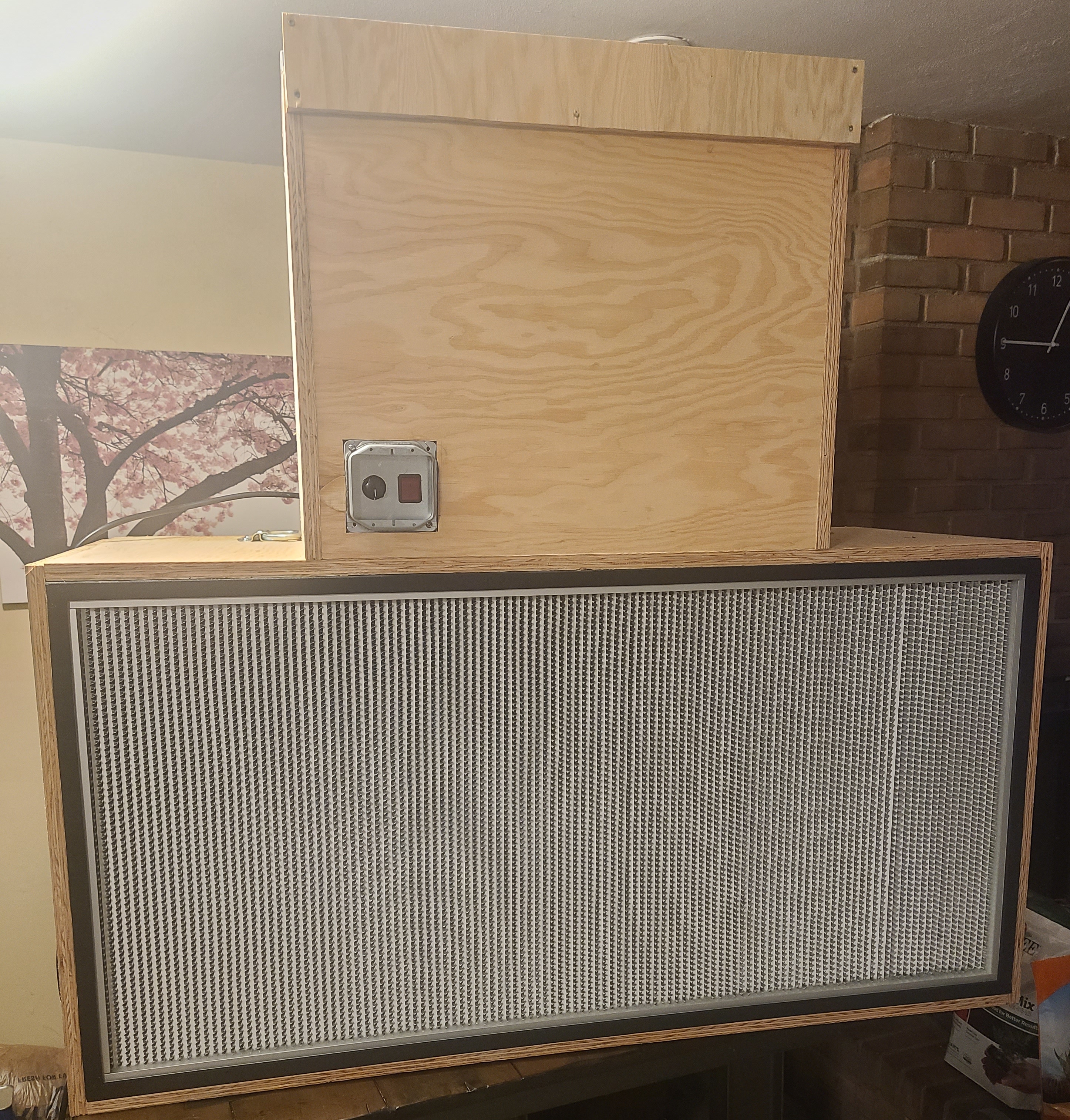
Pretty much the only thing I did right throughout this process was get the opening for the HEPA filter exactly right. It was kind of difficult to screw up because, like the filter, the plywood was exactly 48" across. In the end, the filter fit perfectly and slid right in with only minimal percussive force. I had planned to add a frame on the front to hold the filter in, but decided this wasn't necessary after cutting the pieces for it.
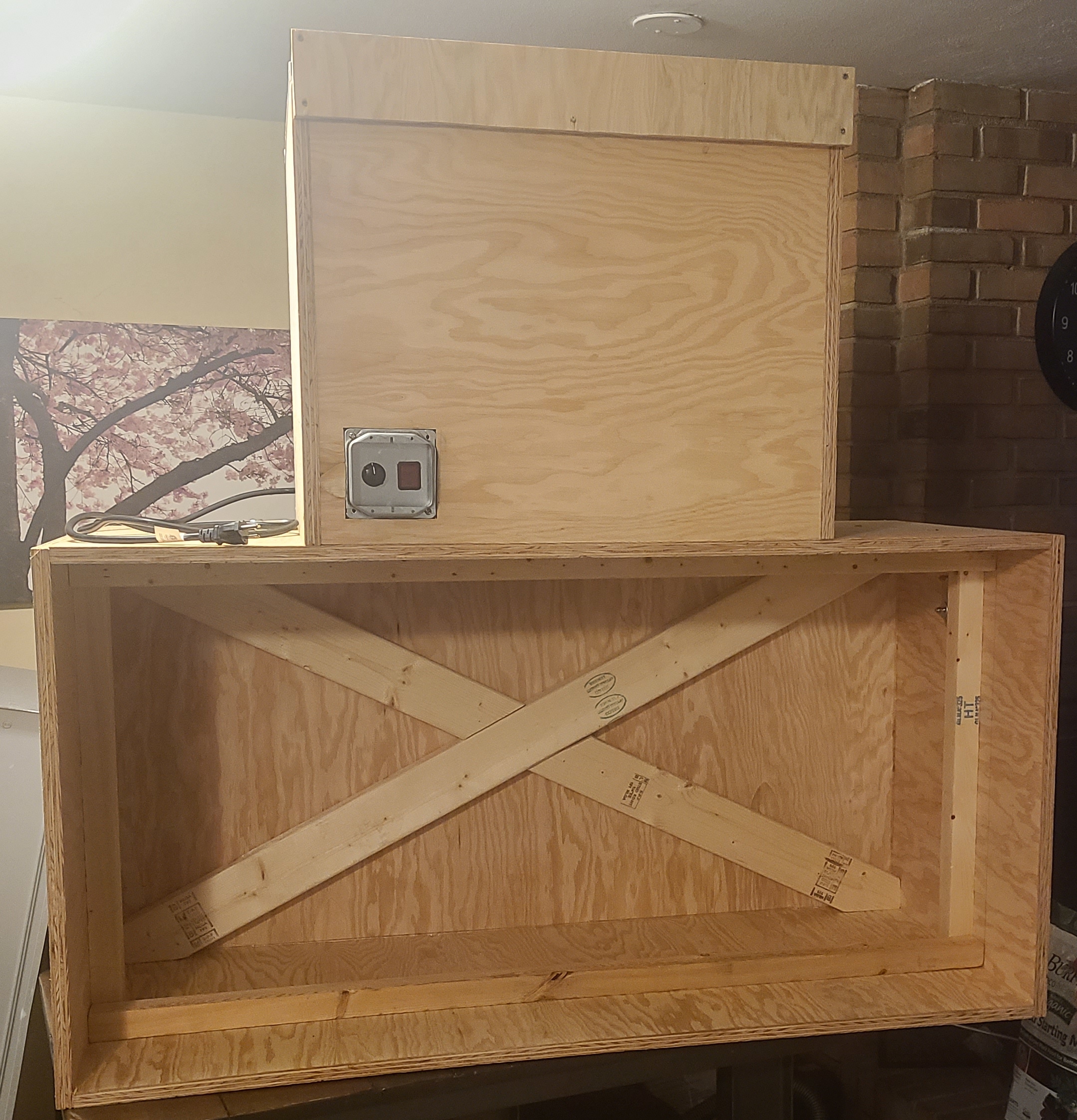
Here's the finished product on my kitchen table before I kicked my kid out of his room and turned into my new lab.
The next thing I should discuss is the fan's wiring. I failed out of electrical engineering because I didn't have the drive to do the insane amount of work required. It was mostly the calculus that was the problem. But I digress. What I'm trying to say is that the electrical work for this thing wasn't terribly complicated, but since I was using mains electricity, I should be very careful.
The Dayton 1XJY1A Direct-Drive Blower is a 1/2 horsepower monster capable of pushing 1654 CFM @ 1.0" SP. That's "cubic feet per minute" (CFM) at 1 inch of static pressure. That means it can lift an inch of water the same way atmospheric pressure lifts millimeters of mercury. I had to look up how they measure this value using a manometer (PDF warning) because I had no idea.
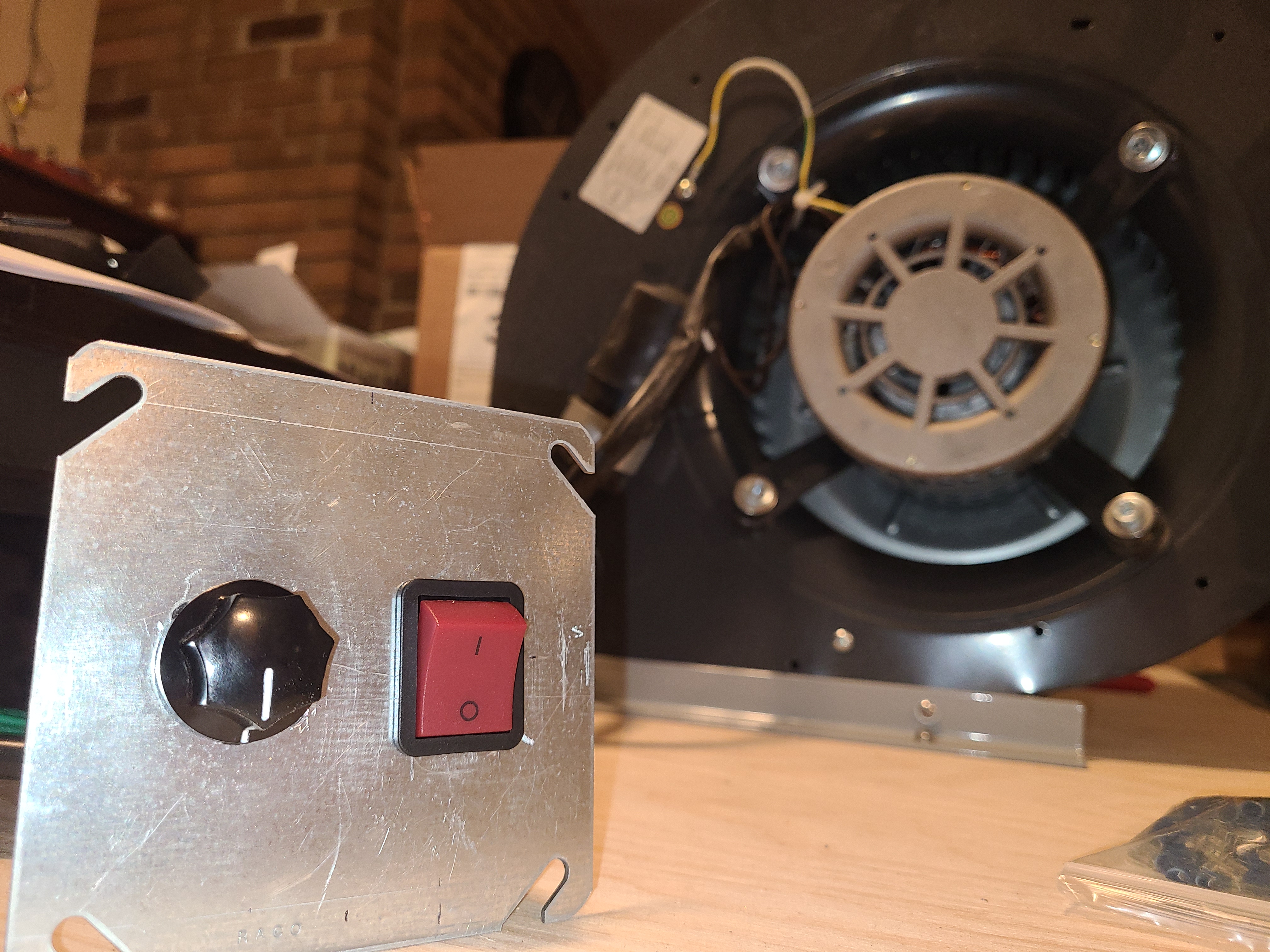
This fan has 4 speeds and doesn't come with a switch, just wires sticking out of it. The rest was up to me. The important thing to note is this fan can pull 9 amps of power at full load, so our switch had to be able to handle that or more. After much more searching than I had expected would be necessary, I found a 5-position rotary switch that could handle 13 amps @ 125 volts. I also wanted the ability to immediately turn the device off in case of an emergency, and the fastest way to do that is a rocker switch. No need trying to remember if "off" is clockwise or counter-clockwise when your cat is about to get sucked into the 1/2 HP blower motor. This is why I don't have cats.
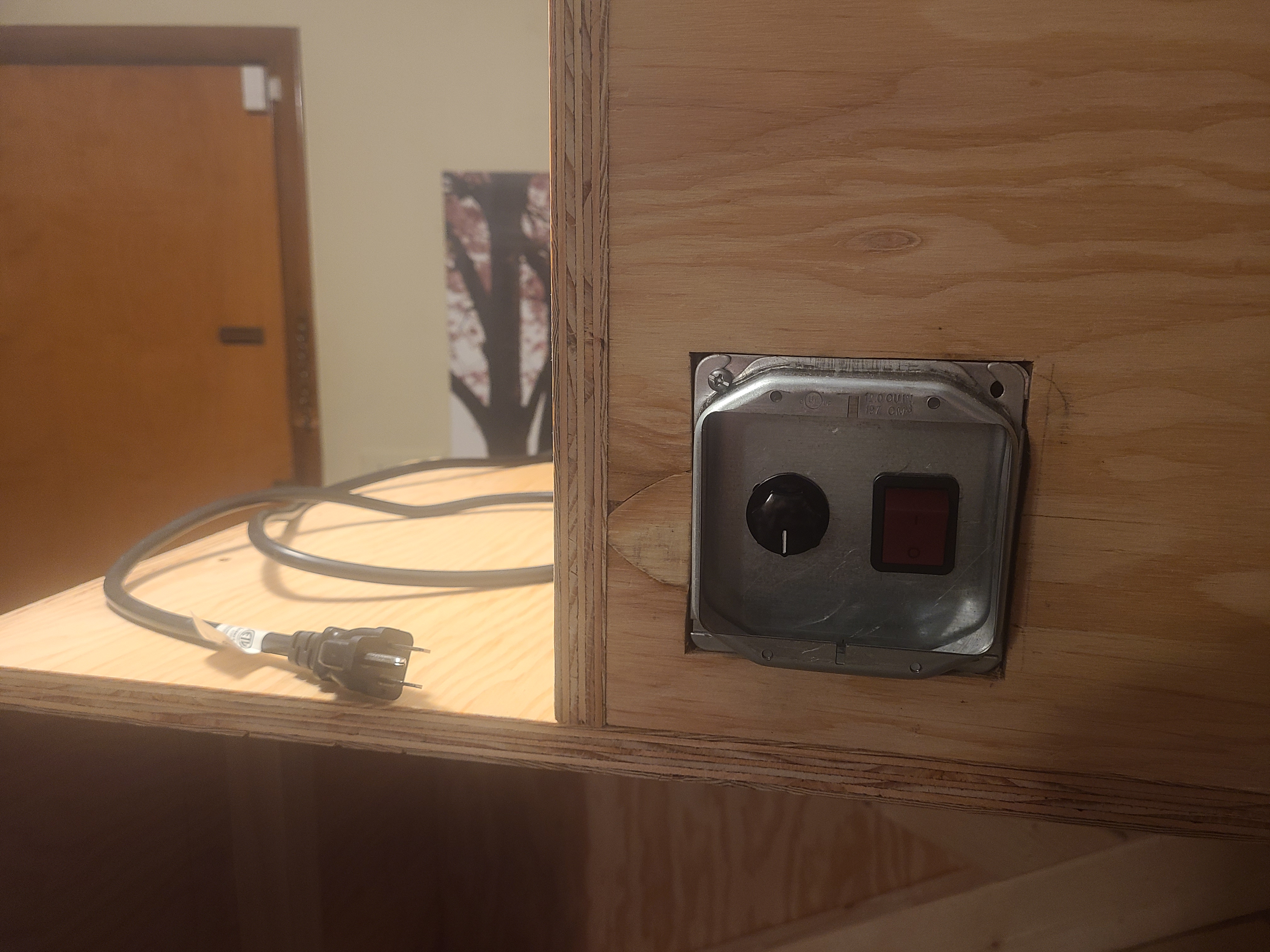
This is what the switch plate ended up looking like. I don't have a machine shop, and this sort of stuff doesn't have pre-made panels, so I bought a blank for a jbox and went to town with a dremel. I don't recommend this. Make friends with a machinist or someone that will let you borrow their water cutting table.
Pretty ominous photo, right? Here's the wiring on the back. I read somewhere that fans start up with the highest speed first, and this matches my experience with all the box fans I have ever owned. So the downward-most position is "off", and moving counter-clockwise are speeds 4, 3, 2, and 1 at the top. If you look closely, you can see the quick connects that I impulse bought as an afterthought when I went to pick up the switches. You might notice how ridiculously close together the conductors are, and how they aren't insulated. The spade connectors are also not the same size as the contacts on the back of the switch, so I went and got the correct ones for the job before final assembly, but neglected to get a picture of this. I'm still a little annoyed how much I paid for a giant box of these things when I only needed a few.
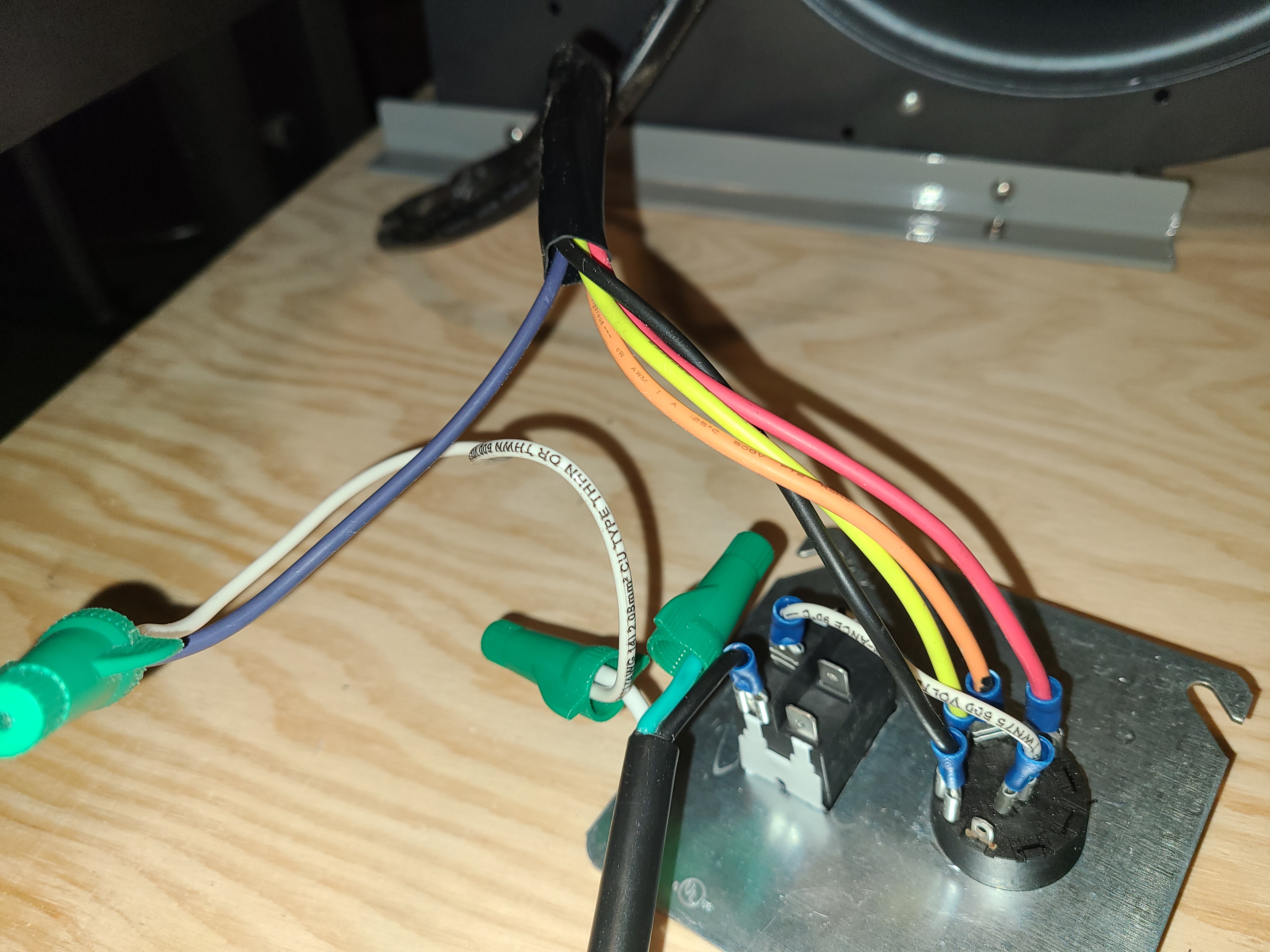
You'll notice the white wire in the middle of the rotary switch is connected to the rocker switch. This is the live/hot wire supplying power to each of the fan's inputs. The other rocker wire is connected to mains power live. The purple wire is the fan's common wire, which you don't want to worry about having switched, it (seems like it?) should always be connected to "negative" or common without the possibility of being disconnected. Perhaps it would have been fine for the common wires to be switched by the rocker as well, but whatever.
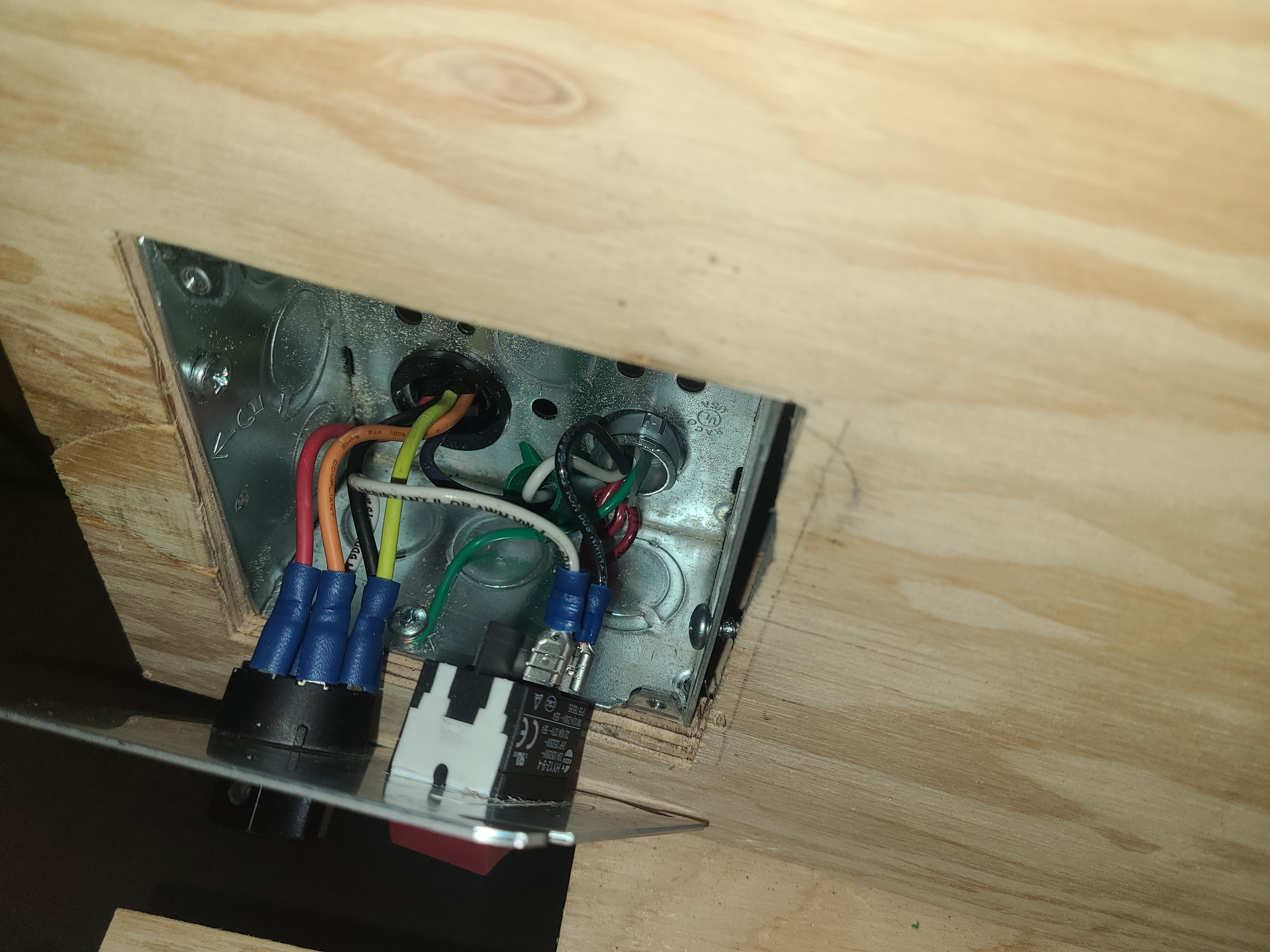
It looks like I lied, I found a picture of the final wiring of the switch using the insulated quick connects. Please notice the green grounding wire connected to the box. This is apparently super important and almost didn't do.
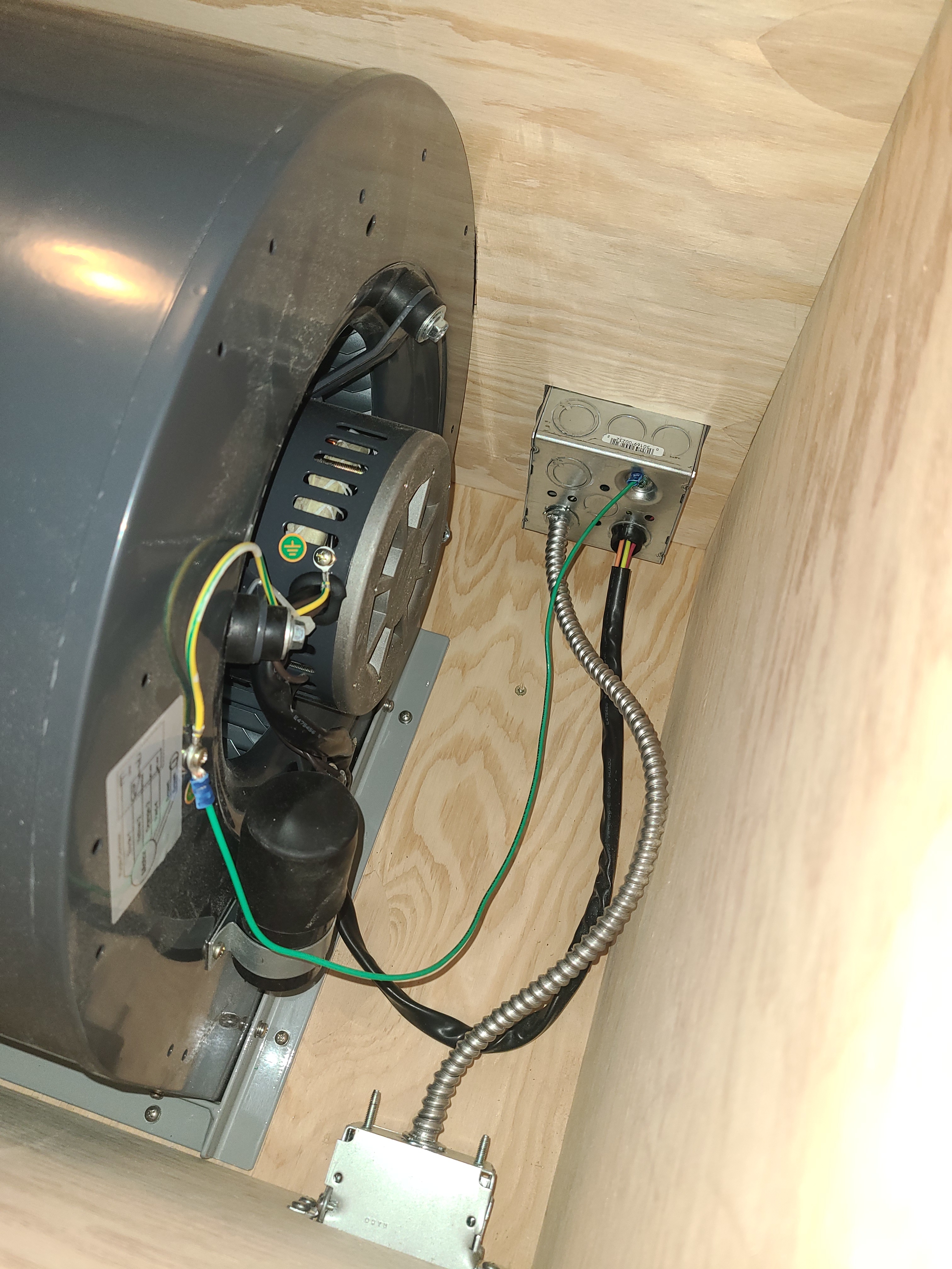
Here's a picture of the blower wired to the switches, and the power supply coming in. The FreshCap tutorial said I should use shielded wire for this, so I bought 25 feet of it because that's the smallest size they had. I also bought 14/3 because I thought that meant two current wires plus a ground wire. It does not. I means there are three voltage wires plus a ground. The third wire, the red one, is a traveller wire used when multiple light switches operate the same light. I did not need this wire so I wrapped it up in each box not touching anything. You'll notice the fan is also properly grounded with the green wire. If you look super close, you might not be able to see how the curved fan housing is resting inside the curved nook I cut into the far wall. I don't think circular saws should be used sideways.
Another thing I want to mention is how much of a pain the shielded wiring was. I bought a couple of these things because they looked like the right thing to buy in the store. I'm no electrician, so I didn't know how to cut the metal-clad cable and ended up just unwinding it a bit and cutting off the sharp parts. Then I screwed the "AC/MC/Flex Snap Lock® Screw-In Connector" into the shielding, which worked fine on the first end because it was the easy end. When you screw it in, the shielding just gets a bit bigger at the overlap because you're working with the open side of the spiral design, but at the other end, it's locked up tight. Eventually I figured out to use pliers and twisted the shielding against itself to increase the diameter, and this finally worked, but only after a lot of swearing and almost giving up. Don't use these. I can't even find a video showing you how to properly install one.
The last thing I will say about the switches is the two-gang mud ring I added. Its purpose is to protect the switches from being accidentally pressed, or sheared off during moving. Here's a close-up of the install.
Here's an image of the inside of the lower box. The back wall is reinforced with a 2x4. Finally had a chance to apply trigonometry in life. The bottom and top horizontal pieces probably do next to nothing for structural support, but they do stop the HEPA from going in too far. The vertical pieces aren't even on the same plane. I don't know what I added them for. I just didn't want the HEPA to take any torsional stress when the unit gets moved around. I'm not sure I achieved that goal, but I sure as fuck made the final product heavy as shit.
The FreshCap tutorial said to use silicone to seal everything, which I did my best at, but ultimately I think this was probably not needed. The cuts were straight enough that basically no air would ever get out. There's a pretty sizeable gap next to the switch box because jigsaws are hard, and really I don't even feel any air getting pulled in through it.
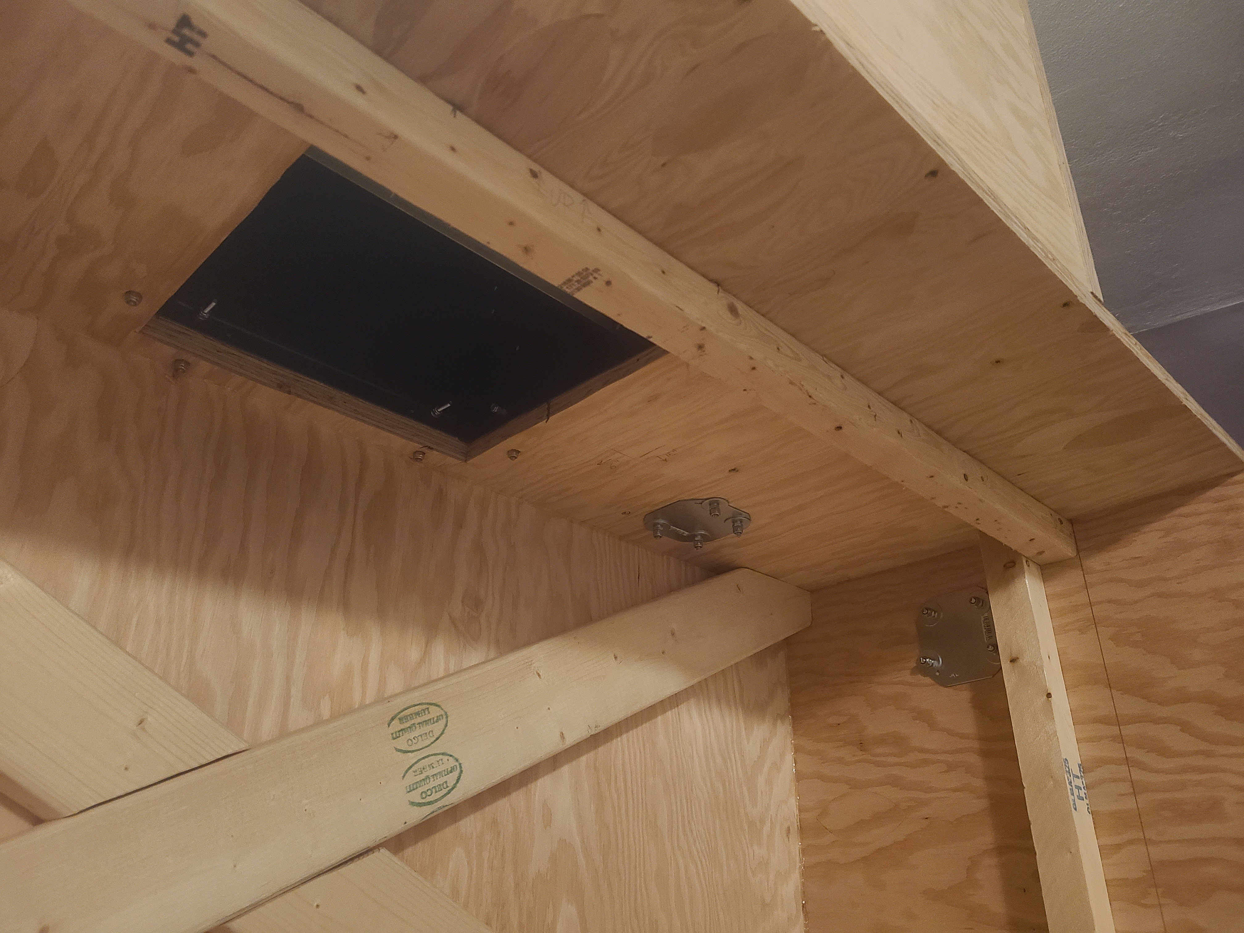
This picture has some detail of the lower box, showing the blower hole (are we still doing phrasing?), and also the reinforced plates that support the pull handles I added. The one on the ceiling has a match on the other side. When I installed them I thought I'd be able to reach on either side of the upper box and carry the whole thing myself. But the final product is just too cumbersome and heavy to do this. I used metal plates to act as giant washers because the last thing I want is for the handle screws to tear out while carrying this bohemoth.
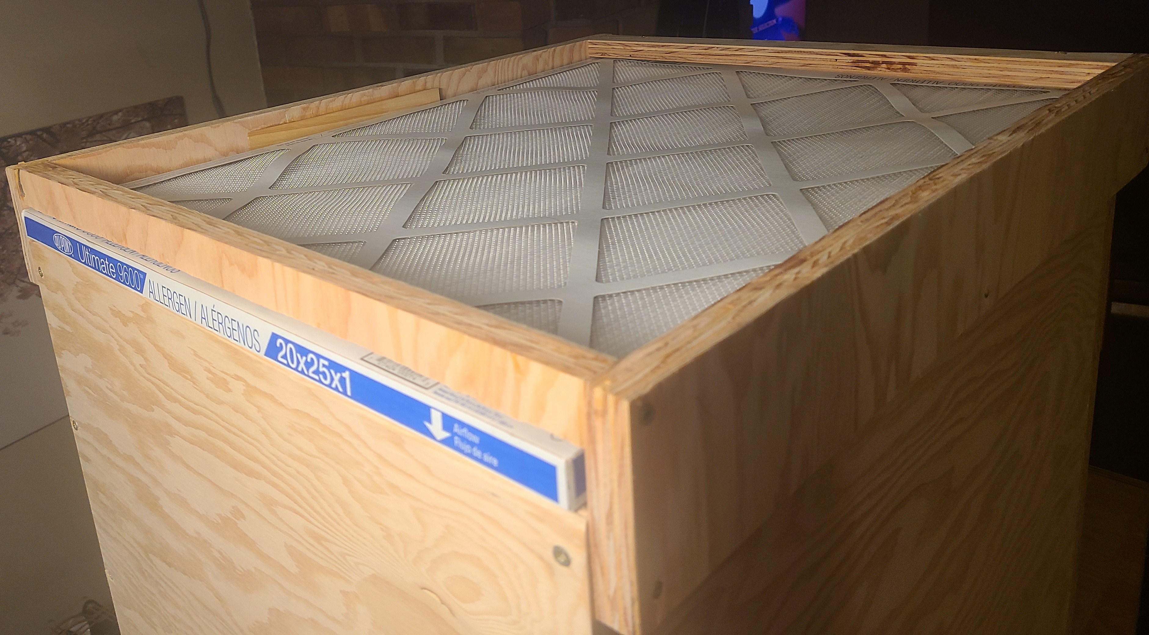
The last picture I'll bother you with is the pre-filter. This is a MERV 13 (probably over-doing it) to remove any large particulate that I don't want to have clogging up the HEPA. I accidentally got this part right, too. The walls of the upper box weren't sized for the filter, but ended up being the exact size of a common filter (25"x20"). If you look close, you'll notice a shim behind the filter in the middle. This is a guide for keeping the filter exactly in place. There's also a couple that aren't visible which hold it tight against the lip on the far side.
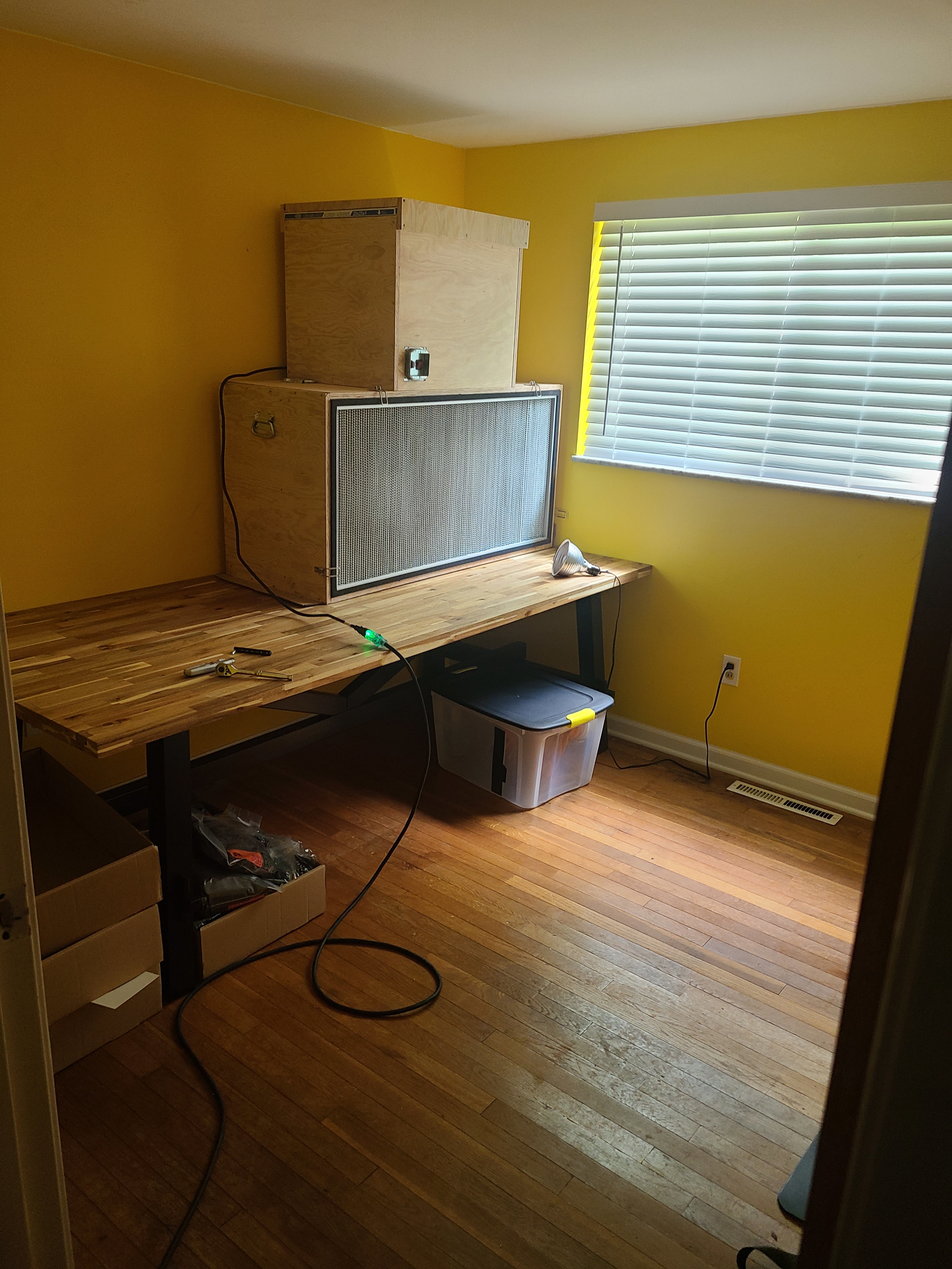
Okay, actual last picture. Moved it into the new lab space after returning the child to the used kid store. A small room with wood floors will be easy keep clean, and the air will be quickly circulated. You might also notice the defeated still-air box laying on the floor, now obsolete, wallowing in the shadow of the mighty laminar flow hood.
It's good I added this picture, because I almost forgot I made a cover for the front of this thing. The HEPA itself is pretty fragile and could easily be ruined during a move. If you look close, you can see the four corner-mount draw latches that are supposed to hold the wood panel I cut from the remaining plywood. I say "supposed to" because they don't do shit, and fall open at every opportunity. They were clearly only meant to be used for a lid that's always using gravity to its advantage, so I had to secure them with a bit of wire I screwed in to keep the latch closed. I could have just used the wire in the first place. I should have bought something like this or this instead.
As you can probably tell, I spent considerably more money and time making this thing myself that I would have just buying it pre-built. Not enough to get a real laminar flow hood though, so it's still a win.
Fin.